Multi-Targets Calculations Realized for Components Produced Cracks with Conventional Material Constants under Complex Stress States
Yangui Yu*
President's Office, Zhejiang Guangxin New Technology Application Academy of Electromechanical and Chemical Engineering, Hangzhou, China
Email address
*Corresponding author
Citation
Yangui Yu. Multi-Targets Calculations Realized for Components Produced Cracks with Conventional Material Constants under Complex Stress States. Engineering and Technology. Vol. 3, No. 1, 2016, pp. 30-45.
Abstract
Author bases on some principles similarly to the genetic genes in the life sciences, adopts the conventional material constants and the data in references, uses the theoretical approach, applies the first strength theory in traditional material mechanics, had derived several new mathematical models. Particularly had proposed complete calculating expressions for the strength calculating criterions, the crack growth rates and the lifetime predictions in whole process; which are to refer to a lot of the complicated equations and calculating methods from micro cracks to macro crocks under the complex stress stages. In addition, in this paper provides yet a detailed example to the threaded connections parts contained micro crack under three-dimensional stress states. This works may be there are practical significances for make linking and communication between the modern fracture mechanics and the traditional material mechanics, for decreasing experiments, for promoting engineering applying and developing to relevant disciplines.
Keywords
Gene’s Principle, Conventional Material Constants, Micro Crack, Macro Crack, Complex Stress State, Calculating Models in Whole Process
1. Introduction
As everyone knows, for the traditional material mechanics, that is a calculable subject, and it has made valuable contributions for every industrial engineering designs and calculations; especially, for some structures under complex stress states, it can also complete the complicated calculations. But it can not be explained for suddenly happened fracture accidents of some structures, for which working stresses are less than the original design permitting ones. In that the material mechanics is only considered for those materials and the structures as the continuous and homogeneous medium to research and calculate, and so that in their calculating models mainly only there are the stresses and the strains and the relating material constants, therefore it can be generally only represented and calculated for those relations between the stresses and the strains about the strength problems. In practice in engineering materials and the structures, usually there are various micro or macro flows (cracks), so it can not solve and calculate ones contained cracks. But in the fracture mechanics and the damage mechanics, which are just based on the local problems as researched objects for the local defects inside materials, to research the driving forces, the crack propagating (damage) rates and the life predictions in the crack growth process, in their calculating models to contain such calculable parameters as the crack size or as the damage variable
 , consequently these subjects can just solve and calculate problems mentioned above. But nowadays
latter these disciplines are all subjects mainly depended on tests; and due to the micro cracks and the macro cracks behaviors there are obviously differences; particularly under complex stress states and under different loading conditions, want to inextenso establish their calculating models about the strengths, the crack propagation rates and the life predictions in the whole process from the micro crack to macro crack growths, which are more difficult and more complicated problems, to pay the manpower and money for experiments are more huge.
Author thinks, in the mechanics and the engineering fields, where are also to exist such a scientific laws as similar to genetic elements and clone technologies in life sciences; and had used the theoretical approach for above the similar principles, proposed some calculation models [1-7]; recently sequentially discovers some new scientific laws, applies the some strength theories in material mechanics, provides some new calculable models for the crack growth driving force, the crack growth rate and life predication in whole process. To try to make the fracture mechanics, step by step become such calculable disciplines as the traditional material mechanics. That way, it may be there are practical significances for decreasing experiments, to stint man powers and funds, for promoting engineering applying and developing to relevant disciplines.
2. The Strength Calculations in Crack Growth Process under Complex Stress States
As everyone knows, the traditional material mechanics had provided famous the first, the second, the third and the fourth strength theory for materials under complex stress states. In the fracture mechanics, Irwin had provided three modes of cracking mode I, mode II and mode III [8]. And in reference it had also provided three types of fracture criterion [9]:
a) When  ;
; ,
,  , it is subjected to the fracture mode I.
b) When  ;
; , , it is subjected to the fracture mode II.
c) When ;,  , it is subjected to the fracture mode III.
Above authors had proposed the criterions in the fracture mechanics, in practice which are by and large coincident with those the strength theories in the material mechanics.
Under complex stress conditions, for the modern fatigue subject, the fracture mechanics and the damage mechanics, author thinks above these disciplines can still continue to use some methods of the strength theories in the traditional material mechanics. Generally speaking, in the linear elastic fracture mechanics, it can adopt the first strength theory or the second strength theory to solve some complex problems; and whether plastic materials or brittle ones, if which are under the three-dimensional stress states, we can also apply the maximal tensile stress theory (the first strength theory) to calculate the equivalent stresses , then can yet be applied for it in the fracture mechanics to derive the equivalent stress intensity factors.
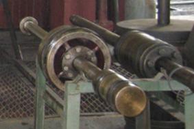
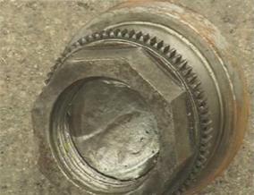
Figure 1. Fracture case subjected to the torsional stress and the tensile stress at piston-rod-end-thread’s location of a compressor.
2.1. The Strength Calculations in Crack Forming Stage (the First Stage)
First of all, here is mention from an instance under complex stresses. For some the threaded connection’s parts made with the carbon steel (figure 1), that is a piston rod of doing reciprocating motions in a compressor, due to stress concentration at the bottom of threads, due to which causes the three-dimentional stresses, so that it is liable to fracture under tensile loading. In this case, it withstands the torsional stress  and the tensile stress
  because is occurred by the torsion-thread’s force, its equivalent stresses is as below
 (1)
(1)
Here we can apply the maximal tensile stress fracture theory (the first strength theory in material mechanics), to calculate the equivalent stress intensity factors. The I-mode-stress intensity factor  [10] to the short crack in the first stage is as following form
 (2)
(2)
Here we can establish its strength criterions is as follow,
 (3)
(3)
Under static loading  is,
is,
 (4)
(4)
Here  is a transition size between two stages from the shore crack to the long crack. The
  is the fracture stress under static tensile loading. But if under fatigue loading, it should be,
 (5-1)
(5-1)
The is a fatigue strength coefficient under tensile fatigue loading. Where
  is a fatigue strength exponent,
  .
.
is defined as the growable crack size, it is also calculable, the is usually between (0.2~0.28) mm
 (5-2)
(5-2)
Based on the first strength theory, we can set up the strength condition to the equivalent stress intensity factor  by equivalent stress , for the short crack is as below,
 (6)
(6)
Here the  just is driving force for the shore crack growth under complex stress states. is the critical I-mode stress intensity factor of the short crack.
2.2. The Strength Calculations in Crack Growth Stage (the Second Stage)
As is well-known, the strength condition of the I-mode long crack is as following one,
 (7)
(7)
Where the  is a correcting factor for influences considered with the crack forms and sizes [11].
So it can also set up its strength condition to I-mode equivalent stress intensity factor  is as below
 (8)
(8)
Where the  is the driving force of the long crack under three-dimensional stress states mentioned above.
In reference [12], it refers to a problem of effective value  about the
  in crack propagation process
Here it proposes to take
 (9)
(9)
Under static loading,
 (10)
(10)
 (11)
(11)
Under fatigue loading,
 ,(12)
,(12)
 (13)
(13)
Here  is a critical size of long crack;
  is an effective size of long crack,
  .
.
3. Calculations of the Crack Growth Rates and the Life Predictions in the First Stage under Complex Stress States
3.1. Calculations of the Short Crack Growth Rates in the First Stage under Complex Stress States
Under complex stress states, Calculations for the short crack growth rates and the life predictions should also imitate the strength theories to derive corresponding models.
Based on above the stress states, and based on the strength conditions and the deriving results mentioned above, with respect to some brittle materials and some linear elastic materials, the short crack growth rate equation corresponded to positive direction curves  and
and  in fig. 2, that are as following forms [13~16].
For the short crack growth rate calculated by I-mode cracking factor is
 (14)
(14)
Where the  is driving force of under fatigue loading. The
  is defined as the equivalent comprehensive material constants, that is derived by the first strength theory. Its physical meaning of the is also a concept of the power [13~16], it is a maximal increment value to give out energy in one cycle before failure. Its geometrical meaning of the is a maximal micro-trapezium area approximating to beeline (fig. 2) that is a projection of corresponding to curve 1 () on the y-axis, also is an intercept between
  . Its slope of micro-trapezium bevel edge just is corresponding to the exponent of the formula (15). The is a calculable equivalent comprehensive-material-constant, for
  , by critical stress intensity factor expression is as below,
 (15)
(15)
If by the fatigue strength coefficient of tensile stress expression is,
 (16)
(16)
Where  is an equivalent critical stress intensity factor under fatigue loading.
  is a critical crack size.
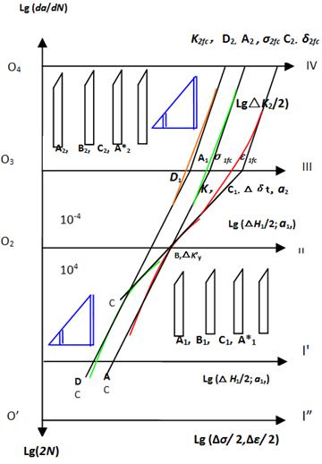
Figure 2. A bidirectional schematic diagram of material behaviors [13~16].
 (17)
(17)
But if  , here it can also apply the correcting method of influence to mean stress by [17], the calculable equivalent comprehensive material constant is as follow,
 (18)
(18)
Where
 (19)
(19)
Therefore,
 (20)
(20)
Where  is an effective short crack size,
 (21)
(21)
It can also adopt following form to calculate [18],
 (22)
(22)
So that the final expansion equations for (14) are as below:
1) By the stress intensity factor calculating method.
For , the short crack growth rate calculated by I-mode cracking factor is as below,
 (23)
(23)
For , the short crack growth rate calculated by I-mode cracking factor is as below,
 (24)
(24)
Here correctiom factor of the effective stress intensity in the first stage,  .
.
2) By the stress calculating method.
For , the short crack growth rate calculated by I-mode cracking is as below,
 (25)
(25)
for , here it can also apply above the correcting method of influence to mean stress, the short crack growth rate is
 (26)
(26)
3.2. Calculations of the Life Prediction in the First Stage under Complex Stress States
The life predicting equation for the short crack growth corresponded to reverse direction curves  and
and  in fig. 2, there are as following forms.
The life calculated by I-mode short crack factor is as follow,
 (27)
(27)
Here it can be selected by as follow:
1) Calculating method by equivalent stress intensity factor :
:
For  , the life calculated by I-mode short crack factor is as follow,
 (28)
(28)
For  , the life calculated by I-mode short crack factor is,
 (29)
(29)
2) Calculating method by equivalent stress  :
:
For, the life calculated by I-mode short crack is as follow,
 (30)
(30)
For , the life calculated by I-mode short crack is as follow,
 (31)
(31)
Their final expansion equations for eqn. (27) is as following forms:
For , the life calculated by I-mode short crack is as follow,
 (32)
(32)
For , the life calculated by I-mode short crack is as follow,
 (33)
(33)
4. Calculations of the Crack Growth Rates and the Life Predictions in the Second Stage under Complex Stress States
4.1. Calculations of the Long Crack Growth Rates in the Second Stage under Complex Stress States
The growth rate equation for the long crack corresponded to positive direction curves  and
and  in fig. 2, that it can apply the Paris’s equation as following forms [19]
 (34)
(34)
Here the  is a material constant,
  ,
,  is a fatigue strength exponent in the second stage. The
  is defined as the equivalent comprehensive material constants, that is derived by the first strength theory. Its physical meaning and geometrical meaning of the are similar with ones in the first stage. The is also a calculable equivalent comprehensive material constant in second stage, which can be calculated with different ways, for ,
 (35)
(35)
 (36)
(36)
Where the  is defined to be the virtual rate, its physical meaning is an equivalent rate in one cycle caused for the precrack contribution, its dimension is similar to the
  -value in reference [20-21]. But author discovers that taking value -"
 " is not needing, if the unit of effective crack size must be adopted with the "
 " to put into the value, where is underneath the square root "
 ". So the can be expressed as following form,
 (37)
(37)
Here  ,
,  ,
, ,
,  .
.
If
 (38)
(38)
 (39)
(39)
Its final expansion equations for equations (34) is as following form:
1) The stress intensity calculating factor method:
For, the growth rate calculated by I-mode long crack factor is as follow,
 (40)
(40)
For , the growth rate calculated by the long crack factor is,
 (41)
(41)
2) The stress calculating method:
For , the growth rate calculated by I-mode long crack factor is as follow,
 (42)
(42)
For , the growth rate calculated by I-mode long crack factor is as follow,
 (43)
(43)
4.2. Calculations for the Long Crack Growth Life Predication in the Second Stage under Complex Stress States
For the life predicting equations of the long crack growth corresponded to reverse direction curves  and
and  in fig. 2, the life calculated by I-mode crack stress intensity factor is as follow,
 (44)
(44)
Here predicting ways for the life cycle number, that can also be selected as follow:
1) Calculating method by equivalent stress intensity factor :
:
For  , the life calculated by I-mode long crack factor is as follow,
 (45)
(45)
For  the life calculated by the long crack factor is,
 (46)
(46)
2) Calculating method by equivalent stress 
The life calculated by I-mode long crack is as follow, For,
 (47)
(47)
For , the life calculated by I-mode long crack is as follow,
 (48)
(48)
Their final life expansion equations for eqn.(44, 45) are as following forms:
For , the Life calculated by I-mode long crack is as follow,
 (49)
(49)
For , the life calculated by I-mode long crack is as follow,
 50)
50)
 (52)
(52)
For , here is to selected eqn (26) and (43) to make the crack-growth-rate-linking-equation corresponded to positive curve  is as below,
 (53)
(53)
5.2. Calculations for Predicting Lifetime in Whole Crack Growth Process
Calculations for predicting lifetime in whole crack growth process, it should also be selected by different stress states for corresponding life equations. For instance, for , here is to select the life calculating equation (30) and (47) or (32) and (48) to make calculations of lifetime in whole process corresponded to positive curve  in fig. 2 is as below,
 (54)
(54)
Or
 (55)
(55)
For , here is to select the life calculating equation (31) and (48) or (33) and (50) to make calculations of lifetime in whole process corresponded to positive curve  in fig. 3 is as follow,
 (56)
(56)
Or
 (57)
(57)
It should point that the calculations for the crack growth rates in whole process should be according to different stress level and loading condition, to select appropriate calculable equations. And here have to explain that its meaning of the eqns (51-53) is to make a linking for the crack growth rates between the first stage and the second stage, in which before the transition-point crack size, its crack growth rate should be calculated by the short crack growth rate equation; and after the transition-point crack size it should be calculated by the long crack growth rate equation. Note that it should not been added together by the crack growth rates for two stages. But it must been added together by the life cycle numbers (56~57) for two stages. About calculation method, it can be calculated by means of computer doing computing by different crack sizes.
6. Calculating Example
6.1. Contents of Example Calculations
To suppose 1: A piston rod which its end by the thread tightening torque to link into the crosshead in a compressor, the piston rod is made with steel 45 [24], its strength limit of material , yield limit
  , reduction of area is
  , modulus of elasticity
 ; Cyclic strength coefficient
  , strain-hardening exponent
  ; Fatigue strength coefficient
 ,fatigue strength exponent
  ,
,  ; Fatigue ductility coefficient
  , fatigue ductility exponent
  ,
,  . And suppose which the critical stress intensity factor value
 under the static loading,
  under the fatigue loading in the first stage, the critical size
  in first stage; the values of the correction factors
  related with the shape, the size and the strength concentration of the part are
  ,
,  and
and  respectively.
To suppose 2: The compressor is continually done in reciprocating motion, the tensile stress  ,
,  at thread’s location caused in motion; the torsional shearing stresses
  ,
,  caused for the tightening threads at piston rod end.
Suppose 3: the long crack shape has been simplified via treatment become an equivalent through-crack, the correction coefficient  of crack shapes and sizes equal 1, i.e.
 .
.
Suppose 4: there is a micro crack of size  at the thread bottom of a piston rod, then to grow to long crack
  , until to
  . Other computing data are all included in table 1.
The computing data are all included in table 1.
Table 1. Computing data.

Table 1. Continued: Computing data.

Table 1. Continued: Computing data.

6.2. To Require Calculating Data
Try respectively calculations:
(1) Try to do strength calculations for the first stage and the second stage: to calculate the equivalent stress intensity factors for the short crack and the long crack, that are at stress concentration location of thread linking under the fatigue loading;
(2) To calculate the crack size at the transitional point between two stages;
(3) To calculate the crack growth rate  at transitional point;
(4) To calculate the short crack growth rate  in first stage from micro crack
 growth to crack
 ;
;
(5) To calculate the long crack growth rate  in second stage from
  to long crack effective size
 ;
;
(6) Calculating for crack growth rate  in the whole process;
(7) To depict the curves of the crack growth rate in whole process.
(8) Calculating for lifetime in the whole process crack growth.
6.3. Calculating Process
It should point the threaded connections made with the carbon steel it is liable to fracture, due to cause the three-dimentional stresses, and due to stress concentration at the bottom of threads when under stretch loading. Therefore, for this case, usually adopt the first strength theory to calculate the equivalent stress intensity factors.
6.3.1. Strength Calculations
(A) Strength calculations in first stage
1. Calculations for the relevant parameter
According to formula (1), to calculate the equivalent stress:
To calculate the maximal equivalent stress,

To calculate the minimal equivalent stress,

To calculate the equivalent stress range value,

According to formula (5), to calculate the critical stress intensity factor at transition point crack size 0.263mm in first stage,

2. Calculations for the equivalent stress intensity factors by calculating formula (6) of the first stage.
According to formula (6), to calculate the maximum and the minimum equivalent stress intensity factor in first stage where it is to the micro crack size  of the piston rod thread bottom, it is as follow:
The maximal equivalent stress intensity factor is,

And the minimal equivalent stress intensity factor is,

1) To calculate the maximal and the minimal equivalent stress intensity factor in first stage that is to the micro crack size of the piston rod thread bottom, it is as below:
The maximal equivalent stress intensity factor is,

And the minimal equivalent stress intensity factor is,

(B) Strength calculations in second stage
1. Calculations for the equivalent stress intensity factors by the calculating formula of the second stage.
1) To calculate the maximal and the minimal equivalent stress intensity factors in second stage that is to the long crack size  of the piston rod thread bottom, it is as follow:
The maximal equivalent stress intensity factor is,

And the minimal equivalent stress intensity factor is,

2) By equation (7) to calculate the maximal and the minimal equivalent stress intensity factor, which they are to the long crack size  at the piston rod thread bottom:
The maximal equivalent stress intensity factor is,

Therefore it causes fracture in this case.
And the minimal equivalent stress intensity factor is,

6.3.2. Calculations for the Crack Growth Rates and the Life Prediction in the First Stage
(A) Calculations for the crack growth rates in the first stage
According to contents and provided data above calculating example 4.1 and 4.3.1, try calculating the growth rates for the micro crack size , to grow to  and on piston rod thread bottom under the fatigue loading.
Calculating the steps and the methods are as below:
1. Calculations for relevant parameters
1) Calculation for the equivalent stress range  and the equivalent stress intensity factors
 ;
;
 .
.
2) Calculation for the equivalent mean stress

3) Calculations for the effective crack sizes  and
and 
According to the formula (21), the effective crack sizes in the first stage is,

According to the formula (13), the effective crack sizes in second stage is,

Comparison for both data, here it should take the smaller size,  .
.
4) Calculation for the equivalent comprehensive material constants  in first stage
According to formula (20), it is calculated as follow,

2. Calculation for crack growth rate at the micro crack size 0.04mm
To adopt the equivalent stress calculation method, according to formulae (20) and (26), it is calculated as below,


3. Calculation for crack growth rate at the crack size 0.5mm.
It is as following result,

Here this growth rate data-value at transition point in first stage end will equal that data-value of the starting point of transition in the second stage.
(B) Calculations for the life prediction in the first stage
According to the contents and provided data in the example 4.1 and the 6.3.2 (A) calculating, to try calculating the life  from the micro crack size
  to the transition crack size
  on piston rod thread bottom.
Calculating the steps and the methods are as below:
According to the equations (20), (27) and (31), calculations for the life in the first stage by the stress calculating method are as follow,

Where


So its life is calculated as follow,

So, the life in first stage is 6956 (cycle).
6.3.3. Calculations for the Crack Growth Rate and the Life Prediction in the Second Stage
(A) Calculations for the crack growth rate in the second stage
According to contents and provided data in calculating example 4.1 and 3.3.1 (B), to try calculating the crack growth rates for at the transition crack size , at long crack size and at on piston rod thread bottom in the second stage.
Calculating the steps and the methods are as below:
1. Calculations for relevant parameters.
1) Calculation for equivalent mean stress to the material
2) Calculation for equivalent stress range and the equivalent stress intensity factor range.
The equivalent stress range to the material is,
To considerate corrections for the stress concentration, the crack’s shape and the size to the part, the equivalent stress range of the part should be calculated as below,

To calculate the equivalent stress intensity factor range at crack size:
Its maximal value  of the equivalent stress intensity factor is,

Its minimal value  is,
is,

So the range value  of the equivalent stress intensity factor is

3) Calculating for the equivalent comprehensive material constant.
Here the influence for mean stress, in practice it is simplified as below

So the equivalent comprehensive material constant by (51) is as below

2. Calculations for long crack growth rate at a crack size
(1) Based on above mentioned data, by the stress intensity factor calculating method (34), its calculating result is as follow,

Here it can also adopt another calculating method---the stress calculating method for long crack growth rate at a crack size
(2) Calculations by the stress calculating method.
1) Calculation for the equivalent comprehensive material constant by (39), it is,

Here, note that this  is equivalent with above mentioned
  The differences between them are only caused on dimensions and units.
2) Calculation for the crack growth rate by (58-2), its crack growth rate at long crack size is as following,


Here, it can see that this  is very approximate with above mentioned

(B) Calculations for the life prediction in the second stage
Based on contents and provided data in the calculating examples 4.1 and 4.3.1(B) and 3.3.3 (A), try to calculate the long crack growth life  from at the transition point crack size to
  .
.
Calculating the steps and the methods are as below:
1) To adopt the equivalent stress intensity factor method.
According the life predicating equation (48), to select relevant parameters to put into it, the life in second stage is as below

6.3.4. Calculations for the Crack Growth Rates and the Life Prediction in Whole Process
(A) Calculations for the crack growth rates in whole process
1. According to the stress state and calculating the result data mentioned above, here to select the crack growth-rate-linking-equation (53), and put into relevant calculating data, for which can be calculated as follow:


2. To take brief crack-rate-linking-calculating-formulas as follow form

Here to get brief crack-rate-linking-calculating-equation is as
 (58)
(58)
 ;
;

So to obtain the crack size at transitional point is  .
.
Here it must point that the crack size of the transition point between two stages, for a material, it can be obtained and calculated by the yield stress; but for a machine part, sometime cannot be found, because it is changed with the work stresses, the shapes and lengths of the cracks, etc.. In this case, it can be to set up a transition size required by designer, for example
3. To calculate the crack rate at transitional point
1) The crack growth rate corresponded to transitional crack size at first stage end point is,

2) The crack growth rate corresponded to transitional crack size at the second stage start point is,

Table 2. Data of crack growth rate in whole process.
| Data point of number | 1 | 2 | 3 | 4 | 5 |
| Crack size (mm) | 0.02 | 0.03 | 0.04 | 0.05 | 0.06 |
|  in the first stage in the first stage
| 3.82×10⁻⁶ | 5.73×10⁻⁶ | 7.64×10⁻⁶ | 9.55×10⁻⁶ | 1.15×10⁻⁵ |
|  in the second stage in the second stage
| Invalid section | 9.10×10⁻⁶ |
Table 2. Continued: Data of crack growth rate in whole process.
| Data point of number | 6Transition point | 7 | 8 | 9 | 10 |
| Crack size (mm) | 0.07275 | 0.1 | 0.15 | 0.25 | 0.4 |
| in the first stage | 1.39×10⁻⁵ | 1.91×10⁻⁵ | 2.87×10⁻⁵ | | |
| in the second stage | 1.39×10⁻⁵ | 2.79 | 6.80×10⁻⁵ | 2.09×10⁻⁴ | 5.85×10⁻⁴ |
Table 2. Continued: Data of crack growth rate in whole process.
| Data point of number | 11 | 12 | 13 | 14 | 15 |
| Crack size (mm) | 0.65 | 0.95 | 1.3 | 1.65 | 2.01 |
| in the first stage | | | | | |
| in the second stage | 1.70×10⁻³ | 3.91×10⁻³ | 7.78×10⁻³ | 1.31×10⁻³ | 0.02 |
4. To depict the crack growth rate curves in the whole process.
By the data in table 2, the crack growth rate curves for two stages and whole process are depicted in figure 3~4.
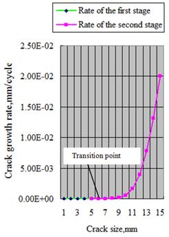
Figure 3. Crack growth rate curves in whole process (in decimal coordinate system).
(a) The curve depicted by the green data point is short crack growth rate is in first stage; (b) The curve depicted by the red data point is long crack growth rate is in second stage.
(c) The transition point size between two stages from micro-crack size 0.02mm to long crack size 2.01mm is just at the sixth point in this example (crack size  ).
).
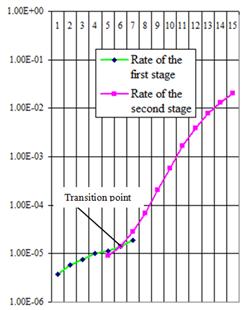
Figure 4. Crack growth rate curves in whole process (in logarithmic coordinate system).
(a) The curve depicted by the green data point is short crack growth rate is in first stage;
(b) The curve depicted by the red data point is long crack growth rate is in second stage.
(c) The transition point size between two stages from micro-crack size 0.02mm to long crack size 2.01mm is just at the sixth point in this example (crack size ).
(B) Calculations for the life prediction in whole process
According to the stress state and calculating the result data mentioned above, here to select the lifetime-equation (56), and put into relevant calculating data, for which can be calculated as follow:

Here we can see that the life of this piston rod in the first stage is 4956 cycle, the life in the second stage is 4000 cycle, the lifetime in whole process it has only 10956 cycle. Because it is made the fracture under the very high stress concentration, which is to occur micro crack of 0.02mm on bottom of the thread under three-dimensional stress stages.
7. Discussions and Conclusions
Some cognitions of author are summarized as below:
(1) Combinations by the traditional materials mechanics and the machines design discipline with the modern the fatigue, the damage mechanics and the fracture mechanics, to inherit their calculable parameters and methods, which these ones can just solve complex problems. Some materials constants  in the fatigue discipline, they can show the inherent characteristic; the cracking variable and the structures of the mathematic models in the fracture mechanics, they can describe the behaviours of the crack propagation process. Author thinks, by means of above which combinations and communications among disciplines, it may be to change and develop the fracture mechanics and the damage mechanics depended on testing; make them to expedite applications in the engineering designs and the computational analysis for safeties and accidents.
(2) The material behaviors between the short cracks and the long cracks there are obvious differences, the primary cause consist in: the short cracks growth to the long cracks forming size , the stiffness of a material is obvious caused to change. The main trait of the material evolving behavior in the first stage is that the short crack growth rate is the linear relation with crack size
 . For the linear elastic materials or the elastic plastic materials under high cycle fatigue loading, the short crack growth driving force is the
  , and token this behavior’s character is the exponent ;
And the main trait of the material evolving behavior in the second stage is the long crack growth to show the nolinear (subduplicate) variable low ( ) with the crack size
 . For the linear elastic materials or the elastic plastic materials under high cycle fatigue loading, the driving force of long crack growth is the
  , and at the moment the stiffness of the material is caused to reduce, token this behavior’s character is changed to be the exponent in this stage.
(3) Under static loading, with the actual fracture stress  and the exponent
  in the fatigue subject, to bring them into the micro fracture mechanics, to establish the calculable model
  , and make it as the critical stress intensity factor in the first stage; and again to bring them into the macro fracture mechanics, to establish the calculable model
  as the critical stress intensity factor in second stage; Under fatigue loading, with the fatigue strength coefficient
  and the fatigue strength exponent
  , to make them bring in the micro fracture mechanics, to establish the short crack calculable model
  , make it as the critical stress intensity factor in the first stage; and again bring them in the macro fracture mechanics, to establish the long crack calculable model
  , make it as the critical stress intensity factor in the second stage. On the other hand, due to the and , the and in the first stage, and the and , the and in the second stage are all the sole material constants with inherent natures, so from their calculable critical stress intensity factors formulae the
  and
and  , and the
  and
and  can also confirm and calculate out the sole critical crack sizes
  and
and  , the
, the  and
and  . Author thinks, above propositions may be there are practical significances for decreasing experiments, for promoting engineering applying.
(4) To use the theories and methods of the first strength theory in traditional material mechanics, particularly for which ways can be calculated under three-dimensional complex stress states, to bring ones into the modem linear elastic fracture mechanics, thereout to derive the equivalent stress intensity factors on the short crack and long cracks, and establish their strength criterions, to solve the strength calculations, the calculations of crack propagation rates, and the calculations of life predictions, this is also a scientific and feasible approach.
(5) Calculations about the crack size at the transition point between two stages, for the materials can be obtained and calculated by the yield stress; but for the machine parts they are changed with the work stresses, the shapes and lengths of the cracks, etc.. In this case, it can be to set up one by designer.
(6) Total conclusion: Based on the traditional material mechanics is a calculable subject, in consideration of the conventional constants there are "the hereditary characters", In view of the relatedness and the transferability between related parameters among each disciplines; And based on above viewpoints and cognitions (1)~(5), then make the fracture mechanics disciplines become calculable subjects, that will be to exist the possibility.
Acknowledgments
1) At first author sincerely thanks scientists J. R. Rice, Irwin, David Broek, Miner, P. C. Paris, Coffin, Manson, Basquin, Y. Murakami,S. Ya. Yaliema,Morrow J D, Keh-Chih Hwang, Tong-Yi Zhang,Chuntu Liu, Shaobian Zhao, Jiazhen Pan, etc, they have be included or no included in this paper reference, for they have all made out valuable contributions for the fatigue-damage-fracture subjects. Due to they hard research, make to discover the fatigue damage and crack behavioral law for materials, to form the modern fatigue-damage-fracture mechanics; due to they work like a horse, make to develop the fatigue-damage-fracture mechanics subjects, gain huge benefits for accident analysis, safety design and operation for which are mechanical equipments in engineering fields. Particularly should explain that author can not have so many of discovery and provide above the calculable mathematical models and the combined figure 1, if have no their research results. 2) Author thanks sincerity the Zhejiang Guangxin New Technology Application Academy of Electromechanical and Chemical Engineering gives to support and provides research funds.
References
- Yangui Yu. The Life Predicting Calculations in Whole Process Realized from Micro to Macro Damage with Conventional Materials Constants. American Journal of Science and Technology. Vol. 1, No. 5, 2014, pp. 310-328.
- Yangui Yu. Life Predictions Based on Calculable Materials Constants from Micro to Macro Fatigue Damage Processes. American Journal of Materials Research. Vol. 1, No. 4, 2014, pp. 59-73.
- Yan Gui Yu. Damage Growth Rate Calculations Realized in Whole Process with Two Kinks of Methods. American Journal of Science and Technology. Vol. 2, No. 4, 2015, pp. 146-164.
- Yangui Yu, The life predictions in whole process realized with different variables and conventional materials constants for elastic-plastic materials behaviors under unsymmetrical cycle loading, Journal of Mechanics Engineering and Automation. 5(2015)241-250. doi: 10.17265/2159-5275/2015.04.006.
- Yangui Yu. The Life Predicting Calculations in Whole Process Realized with Two kinks of Methods by means of Conventional Materials Constants under Low Cycle Fatigue Loading. Journal of Multidisciplinary Engineering Science and Technology (JMEST) ISSN: 3159-0040 Vol. 1 Issue 5, December – 2014.
- Yu Yangui, Sun Yiming, MaYanghui and XuFeng. The Computing of intersecting relations for its Strength Problem on Damage and Fracture to Materials with short and long crack, In: International Scholarly Research Network ISRN. Mechanical Engineering, Volume, Article ID 876396. http://www.hindawi.com/isrn/me/(2011).
- Yangui Yu. The Calculations of Evolving Rates Realized with Two of Type Variables in Whole Process for Elastic-Plastic Materials Behaviors under Unsymmetrical Cycle. Mechanical Engineering Research, (Canadian Center of Science and Education, 2012), 2. (2), PP. 77-87; ISSN 1927-0607(print) E-ISSN 1927-0615 (Online).
- Kare Hellan, Introduction to Fracture Mechanics, McGraw-Hill Book Company, p.2~23.
- V. E. Dragan, P. V. Yasny,Growth mechanism of a small crack under the torsion, Strength Problem, Kiev. 1983, 1, p.38-42, in Russian.
- Yangui Yu. Calculations for Crack Growth Rate in Whole Process Realized with Two Kinks of Methods for Elastic-Plastic Materials Contained Crack, Journal of Materials Sciences and Applications. Vol. 1, No. 3, 2015, pp. 100-113.
- S. V. Doronin, et al., Ed.RAN U. E. Soken, Models on the fracture and the strength on technology systems for carry structures, (Novosirsk Science, 2005), PP. 160-165.(in Russian).
- U. Zerbst, S. Beretta, G. Kohler, A. Lawton, M. Vormwald, H. Th. Beier, C. Klinger, I. C erny´, J. Rudlin, T. Heckel a, D. Klingbeil, Safe life and damage tolerance aspects of railway axles – A review. Engineering Fracture Mechanics. 98, 214–271 (2013).
- Yangui Yu. The Life Predicting Calculations in Whole Process Realized by Calculable Materials Constants from short Crack to Long Crack Growth Process. International Journal of Materials Science and Applications. Vol. 4, No. 2, 2015, pp. 83-95. doi: 10.11648/j.ijmsa.20150402.13.
- Yangui Yu. The Life Predicting Calculations Based on Conventional Material Constants from Short Crack to Long Crack Growth Process. International Journal of Materials Science and Applications. Vol. 4, No. 3, 2015, pp. 173-188. doi: 10.11648/j.ijmsa.20150403.15.
- Yangui Yu. Calculations for Crack Growth Rate in Whole Process Realized with the Single Stress-Strain-Parameter Method for Elastic-Plastic Materials Contained Crack, Journal of Materials Sciences and Applications. Vol. 1, No. 3, 2015, pp. 98-106.
- Yangui Yu. The Calculations of Crack Propagation Rate in Whole Process Realized with Conventional Material Constants, Engineering and Technology. Vol. 2, No. 3, 2015, pp. 146-158.
- Morrow, j. D. Fatigue Design handbook, Section 3.2, SAE Advances in Engineering, Society for Automotive Engineers, (Warrendale, PA, 1968), Vol. 4, pp. 21-29.
- Y. Murakami, S. Sarada, T. Endo. H. Tani-ishi, Correlations among Growth Law of Small Crack, Low-Cycle Fatigue Law and, Applicability of Miner’s Rule, Engineering Fracture Mechanics, 18, (5) 909-924, (1983).
- Paris, P. C., and Erdogan F., A critical analysis of crack propagation lows, Journal of Basic Engineering, Vol.85, 1963, pp.525~536.
- S. Ya. Yaliema, Correction about Paris’s equation and cyclic intensity character of crack, Strength Problem.147, (9) 20-28(1981).(in Russian).
- Yangui Yu. The Calculations of Evolving Rates Realized with Two of Type Variables in Whole Process for Elastic-Plastic Materials Behaviors under Unsymmetrical Cycle. Mechanical Engineering Research. Canadian Center of Science and Education 2012; 2. (2): 77-87; ISSN 1927-0607(print) E-ISSN 1927-0615 (Online).
- Yangui Yu. Life Predictions Based on Calculable Materials Constants from Micro to Macro Fatigue Damage Processes, American Journal of Materials Research. Vol. 1, No. 4, 2014, pp. 59-73.
- Yangui Yu. The Predicting Calculations for Lifetime in Whole Process Realized with Two Kinks of Methods for Elastic-Plastic Materials Contained Crack, Journal of Materials Sciences and Applications. Vol. 1, No. 2, 2015, pp. 15-32.
- China Machine Press, Mechanical design handbook, New Edition, Volume 5.31~124~135; 31-57~60; 31-134~136. (in Chinese).