| 1. | ||
| 2. | ||
| 3. | ||
| 4. | ||
| 5. | ||
| 6. | ||
Plasma Process of Silicon Production for Photovoltaic Power Generation
Petrov Stanislav1, *, Korzhyk Volodymyr2
1The Gas Institute of the National Academy of Sciences of Ukraine, Kyiv, Ukraine
2The E. O. Paton Electric Welding Institute of the National Academy of Sciences of Ukraine, Kyiv, Ukraine
Email address
 (P. Stanislav)
 Citation
Petrov Stanislav, Korzhyk Volodymyr. Plasma Process of Silicon Production for Photovoltaic Power Generation. Engineering and Technology. Vol. 3, No. 5, 2016, pp. 74-88.
Abstract
The continuous technological process of «solar» silicon production by the method of plasma pyrolysis of monosilane is investigated. The time of decomposition, e.g. at 1800°C, is 2×10⁻⁵ s. At a plasma velocity of about 1000 m/s, decomposition of monosilane will take place at a distance of 2 cm. The energy consumption: at useful plasmatron power W = 100 kW, volume ratio VAr/VH2 = 0.2/0.8 and reaction zone length L = 0.06 m, we obtain that min QSi = 1.69 kW×h/kg Si, GSi = 50 kg/h Si. Considered was the problem of modelling of the steady-state process of cooling and condensation of silicon vapours and molten silicon droplets produced as a result of interaction of monosilane with a plasma jet. The effect discovered when the condensation reactor is combined with the granulator, i.e. where the processes of condensation of silicon vapours into a liquid film and transformation of flow of this film into the droplet one simultaneously take place on its working surface, leads to formation of a new concept of the condenser – granulator. It is possible to create the high-efficient equipment for continuous production of cheap high-purity silicon with low capital and service expenses basing on this process.
Keywords
Silicon, Plasma, Monosilane, Condensation, Liquid Film, Skull, Granulator
1. Introduction
The purpose of the work is to develop the process and equipment for plasma-chemical production of silicon for solar power generation. In this case take place the decomposition of monosilane through a gas phase of silicon followed it as homogeneous condensation in silicon particles and heterogeneous one – on the melt surface. There was studied the pyrolysis of gas of monosilane precursor in hydrogen plasma. It confirms that there are no any thermodynamic and kinetic prohibitions and limitations on thermal decomposition of monosilane at temperature above silicon melting from gaseous state to vapor one, then to liquid one. It is possible to create the high-efficient equipment for continuous production of cheap high-purity silicon with low capital and service expenses basing on this process. The theoretical limit on power consumption for plasma-chemical production of silicon is 3...5 kW h/kg of SoG-Si. At 100 kW useful power of plasmatron the efficiency as applied to silicon will be about 25 kg/h. The application of plasma pyrolysis of monosilane allows organizing the continuous process of silicon production unlike the traditional technology of cyclic Siemens CVD technology. The high rate of pyrolysis reactions (1∙10-5 s) due to an elevated process temperature above the melting point of silicon (> 1415°C) provides a relatively small size of the working zone (0.1... 0.2 m), as well as the dimensions and the total weight of the reactor. This investigation of the process and equipment for plasma-chemical production of silicon for photovoltaic power generation serves as a basis for elaboration of the engineering method for their calculation. Modelling of the monosilane pyrolysis plasma module of the plasma-chemical reactor for continuous production of silicon melt is done with a maximum possible approximation to the real processes and equipment.
2. Thermodynamic Equilibrium
The first part of the work includes calculation of thermodynamic equilibrium, optimisation of power consumption and yield of the target product. This investigation serves as a basis for elaboration of the engineering method for their calculation which includes:
• generation of the hydrogen plasma jet with a mean mass temperature of 2000-3000°C and rate of 400-800 m/s;
• providing of transverse split jet-like inflow of precursor gas (monosilane) to a sweeping-away flow of the hydrogen plasma at a weight ratio of SiH4/H2 ranging from 1/1 to 5/1, formation of the two-phase (hydrogen + silicon vapours) flow with a temperature of 1600 - 1800°C, and its tangential introduction to the vortex chamber of the reactor with a wall temperature of 1400 - 1500°C;
• primary separation of silicon vapours and hydrogen – under the effect of inertia forces of vortex motion due to a large difference between the weights of silicon and hydrogen the former is pressed to the wall and partially transforms into the melt, which flows down to the reactor bottom;
• Secondary (final) separation of remaining silicon vapours and hydrogen at a high-temperature (1600 - 1800°C) with an opposite motion of hydrogen and silicon melt.
• providing of transverse split jet-like inflow of precursor gas (monosilane) to a sweeping-away flow of the hydrogen plasma at a weight ratio of SiH4/H2 ranging from 1/1 to 5/1, formation of the two-phase (hydrogen + silicon vapours) flow with a temperature of 1600 - 1800°C, and its tangential introduction to the vortex chamber of the reactor with a wall temperature of 1400 - 1500°C
• primary separation of silicon vapours and hydrogen – under the effect of inertia forces of vortex motion due to a large difference between the weights of silicon and hydrogen the former is pressed to the wall and partially transforms into the melt, which flows down to the reactor bottom
• Secondary (final) separation of remaining silicon vapours and hydrogen at a high-temperature (1600 - 1800°C) filter with an opposite motion of hydrogen and silicon melt.
The plasma-chemical reactor according to the developing method is shown in Fig. 1 [1].
Fig. 1. Schematic view of the plasma-chemical reactor for continuous production of silicon melt., a - pyrolysis module, b - Reactor with coolant.
In fact, the work under the first part provides for solving the problem of modelling of the plasma module that implements pyrolysis of monosilane to produce silicon aerosol. Modelling of the monosilane pyrolysis plasma module of the plasma-chemical reactor for continuous production of silicon melt is done with a maximum possible approximation to the real processes and equipment (Fig. 2) [2].
Assumptions:
1. Plasma at the exit section of the plasmatron nozzle in zone d1 ahead of the zone of mixing with monosilane is in a state of thermodynamic equilibrium
2. Length L2 of the plasma and monosilane mixing zone coincides with length of the zone of complete decomposition of monosilane into hydrogen and atomic silicon
3. monosilane pyrolysis products in the channel (zone d2) are in a state of thermodynamic equilibrium
4. Channel L3 behind zone d2 is a kinetic zone, wherein the following processes occur: 4.1. Condensation of silicon vapours on the wall to form the silicon melt and blowing out of the melt with a gas flow; 4.2. Formation and growth of silicon particles to form the two-phase flow of H2+Ar+Si (particles)
5. The flow is assumed to be adiabatic
6. The chemically developing system consists of the parts described by thermodynamic parameters, which are in two states: non-mixed cold feedstock, and homogeneous mixture of feedstock and plasma in the quasi-equilibrium state at a given time moment
7. Chemical transformations in the system can take place only in the quasi-equilibrium state and are a set of transformations occurring by the preset mechanism of elementary chemical reactions with known thermal effects and rate constants determined by the Arrhenius dependence
8. The given chemical transformations have no substantial effect on the mass exchange processes. A limiting stage is turbulent mixing
9. A change in thermodynamic conditions from zone d1 to zone d2, which determine the quasi-equilibrium state, is considered on the basis of the generalised equation of thermal balance derived in an approximation of the equations of thermodynamics, equation of state of an ideal gas and continuity equation
10. Calculation of flow in the channel is made on the basis of mean-mass parameters
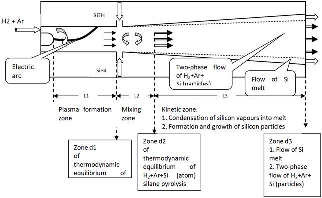
Fig. 2. Schematic of monosilane pyrolysis module with characteristic zones.
According to thermodynamic calculations, monosilane decomposes into silicon and hydrogen at a temperature as low as the ambient temperature. However, the rates of reaching the thermodynamic equilibrium at low temperatures are very low. Reaching the thermodynamic equilibrium during the monosilane decomposition process is characterised by the presence of an induction period, which greatly depends upon the temperature [3, 4, 5].
The time of induction can be estimated from the following dependence:
![]()
Where Eu = 255 kJ/mole
Increase in temperature of the reaction of thermal decomposition of monosilane up to the melting temperature, at which it is planned to conduct the process, is several orders of magnitude higher than the rate of reaching the thermodynamic equilibrium in the SiH4-Si(c)-Si-H2-Ar system.
The complex mechanism of the process of thermal decomposition of monosilane can be reduced to the following main stages:
![]() (1)
(1)
![]() (2)
(2)
According to reaction (1), the rate of the reversible reaction of decomposition of monosilane is as follows:
![]() (3)
(3)
Given that the concentration of SiH2 almost instantaneously reaches the equilibrium, i.e. the rate of decomposition of SiH2 according to reaction (2) is equal to that of production of SiH2 as a result of reaction (1), we can write down that
![]()
which, after transformation, yields:
![]() (4)
(4)
By substituting (4) to (3), we obtain:
![]() (5)
(5)
Within the range of working temperatures of the monosilane decomposition reaction equal to 1500-2000°C (the range above the melting point of silicon), the constant of back reaction (1), k-1, is much lower than that of the rate of reaction of decomposition of SiH2, i.e. k-1<<k2.
As a result, the rate of the monosilane decomposition reaction can be reduced to the first-order equation:
![]() (6)
(6)
In compliance with data of different studies [3, 4], as a result of processing of the experimental data obtained over a very wide range of variations in temperature (723-1730 K) and pressure (10-3-105 Torr) in the reaction volume, we calculated preexponential factor k0 and activation energy E, the values of which are given in Table 1.
Table 1. Arrhenius’ parameters for reaction of decomposition of monosilane.
| Pressure, atm | E, kJ/mole | k0, s-1 |
| 1.32×10⁻⁶ | 214.4 | 1.5×10⁷ |
| 1.32×10⁻⁵ | 214.4 | 1.5×10⁸ |
| 1.32×10⁻⁴ | 214.4 | 1.5×10⁹ |
| 1.32×10⁻³ | 214.4 | 1.5×10¹⁰ |
| 1.32×10⁻² | 214.8 | 1.5×10¹¹ |
| 0.132 | 218.6 | 1.8×10¹² |
| 1.32 | 223.6 | 1.7×10¹³ |
Investigation of physical-chemical, heat and mass exchange, and thermal gas-dynamic processes occurring at increased temperatures by modelling involves problems related both to finding compositions of the reaction products and to evaluation of thermodynamic and transport properties of high-temperature environments. In turn, these properties depend upon the composition of working media, i.e. multi-component mixtures of dissociating gases and individual condensed phases, and are functions of the state: temperature, pressure, specific volume, etc. Fig. 3 show the calculated temperature dependencies of equilibrium compositions of products of reaction SiH4 = SiH2 + Si + H2 for a case where the condensation of silicon is prohibited. These are the important dependencies. They are valid for the real process we develop, where decomposition of monosilane passes through a stage of gaseous silicon with subsequent homogeneous condensation into silicon particles, in contrast to standard low-temperature (max. 1000°C) processes of deposition of silicon from monosilane or from trichlorosilane on the surface in rod-type or fluidised-bed reactors.
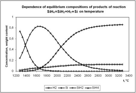
Fig. 3. Temperature dependence of equilibrium composition of products of reaction.
SiH4 = SiH2 + H2 + Si
Analysis of equilibrium compositions of the SiH4 = SiH2 + H2, SiH2 = Si + H2 and SiH4 = SiH2 + Si + H2 reaction products depending upon the temperature for a case where the condensation of silicon is prohibited shows that mechanisms of high-temperature decomposition of monosilane and subsequent growth of the particles will be fundamentally different from those of the traditional low-temperature processes.
According to the adopted flow diagram of the processes of high-temperature decomposition of monosilane SiH4 to model the last stage, i.e. condensation of silicon vapours, it is necessary to know dependence of pressure of the saturated silicon vapours upon the phase transition temperature. The difference between the partial pressure of silicon vapours, PSi, in a gas mixture and pressure of the saturated silicon vapours, P*Si, determines the concentration head which, in turn, determines the rate of inter-phase exchange. Calculations for evaluation of boiling temperature of silicon under different pressures were made to determine the temperature dependence of pressure of the saturated silicon vapours. Approximation of these data yielded the following temperature dependence of pressure of the saturated silicon vapours:
PSi(t)= - 1.5370E+01 + 3.7568E-02×t – 3.6589E-05×t2 + 1.7781E-08×t3 – 4.3212E-12×t + 4.2122E-16×t, the graphical form of which is shown in Fig. 4.
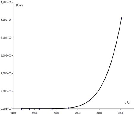
Fig. 4. Temperature dependence of pressure of saturated silicon vapours.
Results of the above thermodynamic calculations were used to develop the software and software support for calculation of material and energy balances of the plasma process of decomposition of monosilane. Main parameters of the process of thermal decomposition of silane were calculated at the set values of power of the plasmatron and its design characteristics by setting various ratios of monosilane and plasma gas (H2 + Ar), the composition of which was also varied.
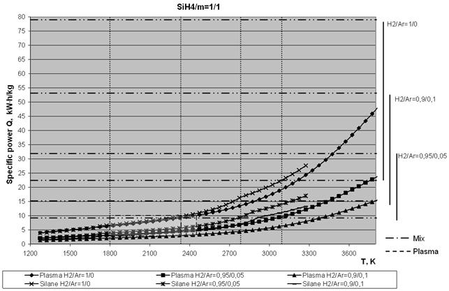
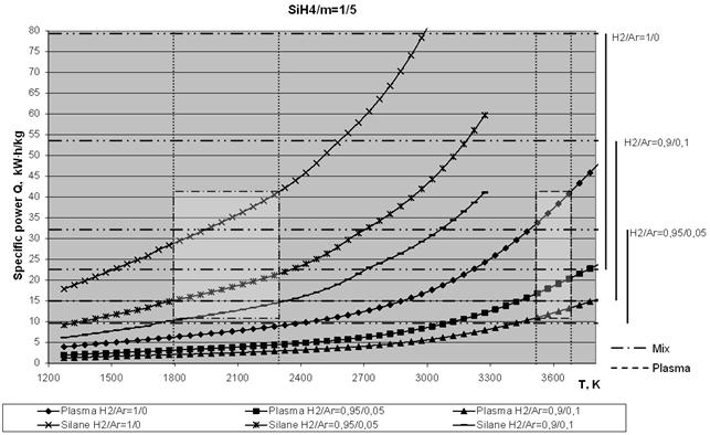
Below, Figs. 5a and 5b show temperature dependencies of the specific consumptions of power required to produce 1 kg of silicon at different ratios of monosilane to plasma gas weight contents (SiH4/m = 1/1 and 1/5). The ratios of H2/Ar volume contents were 1/0, 0.9/0.1 and 0.95/0.05. The diagrams show the set limits of a working temperature of pyrolysis products, i.e. 1800 - 2300 K (left hatched rectangle). The required temperature range of the plasma gas (right hatched rectangle) was determined from the set limits of the working temperature. Here a limitation is imposed on the attainable specific power of the plasmatron, i.e. it is assumed to be within a range of 2 - 7 kW×h/nm3 of the plasma gas.
Analysis of the curves shown in Figs. 5 indicates that the yield of silicon in plasma pyrolysis of monosilane strongly depends upon the plasma gas composition. This is illustrated in Fig. 6, which shows dependence of the power consumption on the degree of dilution of the plasma gas with monosilane for a working temperature of the mixture equal to 1700 K, as well as on the plasma gas composition
a
b
Fig. 5. Temperature dependencies of the specific consumptions of power required to produce 1 kg of silicon at different ratios of monosilane to plasma gas weight contents (SiH4/m): a - 1/1 and b - 1/5.
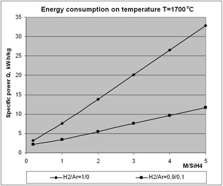
Fig. 6. Dependence of the power consumption on the degree of dilution of the plasma gas with monosilane.
It should be noted that an addition of argon to hydrogen in the plasma mixture provides substantial reduction of the specific costs of production of silicon (Fig. 6).
The Figure 7 given below show results of the calculations of working parameters for the reactor (Fig. 1 a) and plasma module according to the scheme shown in Fig. 2 at a plasmatron power of 100 kW.
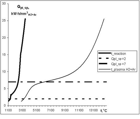
Fig. 7. Dependence of the specific capacities of (H2-Ar) of a plasma stream (a thin line) and diluted with monosilane ((SiH4) of the same stream (a thick line) from temperature. The working range of specific capacities (2 - 7 kW·h/nm3) is between horizontal lines.
Results obtained above are estimates of the maximal possible amount of the processed silane (produced silicon). It is assumed that the thermodynamic equilibrium takes place in this case, i.e. the total amount of silane fully decomposes or, at least, the amount of non-reacted silane corresponds to its thermodynamically specified value. This assumption does not impose any limitation on the time of dwelling of the mixture in the reaction zone.
At the same time, the estimated time of dwelling of the mixture in the reaction zone shows that, despite a high rate of the decomposition process (Fig. 8), by no means it has always enough time to be completed.
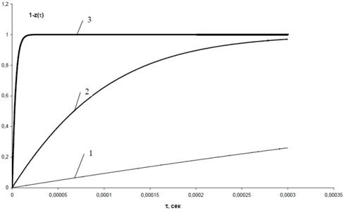
Fig. 8. Rate of decomposition of monosilane at different temperatures.
1 – t = 1200°C; 2 – t = 1600°C 3 – t = 1800°C
The efficiency of performance of the decomposition process at different temperatures in the reaction zone, tr, can be evaluated in the first approximation by using the results characterising the amount of the processed monosilane (produced silicon) and time of dwelling in the reaction zone, together with the amount of monosilane decomposed during this time (1 – z(t)), which is calculated. Proceeding from the requirement of a minimal power consumed for production of 1 kg of silicon, it is possible to determine optimal working temperature tr_opt for the given design of the device and corresponding values of maximal productivity GSi kin, minimal specific power consumption min QSi sp kin, specific plasmatron load Qpl sp opt, and maximal plasma temperature tpl opt.
Below (Fig. 9) we give results for a constant value of m = 0.2, which reflects the ratio of weight contents of plasma agent Ar + H2 and silane SiH4, and which corresponds to the values of g calculated from the following formula at different ratios of hydrogen to argon volume contents:
g = (m×MSiH2 /MAr+H2),
Calculations for the 100 kW plasmatron were made by using the following design parameters:
D1 = 0.016 m, D2 = 0.030 m, and L = 0.0254 m.
Increase of the time of contact in the mixer chamber, e.g. by increasing its length L, decreases the optimal working temperature and, hence, temperature of the jet at the exit section and specific load on the plasmatron, the maximal productivity of the device simultaneously rising. It can be seen that increase in length L of the mixer chamber from 0.0254 m to 0.06 m for a variant of W = 100 kW, VAr/VH2 = 0.2/0.8 and g = 0.6667 provides an 18% increase in productivity for the target product, the values of specific power consumption and temperature of the plasma and reaction medium being markedly decreased.
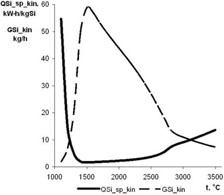
Fig. 9. Dependence of maximal productivity GSi kin and minimal specific power consumption min QSi sp kin from temperature.
In view of the absence of commonly accepted opinions on the mechanism of thermal decomposition of silane with simultaneous formation of the condensed (solid or liquid) phase of silicon, as well as absence of the reliable theoretical or experimental data on the high-temperature and high-productivity processes under consideration [6-11], the following approach was used at this stage of the work. It is assumed that an ideal mixing takes place and a temperature corresponding to the energy (thermal) balance is established at the first stage of injection of silane to the plasma jet formed from the hydrogen and argon mixture. In this case, the average relaxation time for gases participating in this process can be used as a measure of the process duration. According to the accepted measure of the time of establishment of thermal equilibrium, and knowing the rate of motion of the gas phase in a given element of the structure, it is possible to estimate the length of a region of the reaction zone to be regarded as a mixing heat exchanger. Then the process of thermal decomposition of silane begins. The high degree of oversaturation of silicon vapours leads to formation of the finely dispersed condensed phase (aerosol). This process can be described as a set of the simultaneously occurring processes, such as formation of primary nuclei with critical radius Rcr and their subsequent growth as a result of heat and mass exchanges between the particles and gas phase.
Both processes can be regarded as a sinks for vaporous silicon. The balance of the rates of transition of vaporous silicon to the gas phase and its consumption determine the current concentration (partial pressure) of vaporous silicon. In turn, the current value of the concentration affects the rate of decomposition of monosilane, critical radius and quantity of the condensed phase nuclei formed per unit time, as well as the rate of growth of individual particles.
As decomposition of monosilane is an endothermic process, it can be considered to be a sink from the energy (heat) standpoint. Condensation of silicon vapours leads to a release of energy related to the phase transition. Therefore, the process of formation of the condensed phase is a source of the thermal energy. Relationship of the two processes determines the current value of temperature in the reaction volume.
Aerosol particles may be in a solid or liquid state, depending upon the working temperature at which the process of decomposition of silane takes place to form the condensed phase of silicon. Therefore, different mechanisms of agglomeration of the particles are considered in literature [3, 8, 10].
Speaking about minimization of real energy consumption per unit of produced silicon (amount of electricity taken from the mains) kW/kg, the base here is thermodynamic equilibrium specific energy consumption for the pyrolysis of monosilane. Under the operating temperature range of 1900 - 2100°C in the pyrolysis zone, the maximum yield of silicon on the basis of net power is expected to be in the range of 2 - 4 kW•h/kg Si. Taking into account the energy loss, this value will increase in 1, 5 - 2 times.
The calculations of pyrolysis and condensation reactor are performed in accordance with the logic of the process and included mathematical modeling, done using standard and specially designed programs, as well as engineering calculations. Developed mathematical model was used to calculate the steady (stationary) process of cooling and condensation of silicon vapor and droplets of molten silicon, that appear due to the interaction of silane (SiH4) with a high-temperature plasma jet, consisting of argon and hydrogen, taken in different proportions. This software, in addition to variation of geometric and thermophysical parameters of the structural materials of the setup, also allows to investigate the effect of individual process parameters - power of plasmatron, temperature and flow rate of cooling water, an additional supply of heat in some areas. Subsequent calculations allow to determine the flow of molten silicon particles and their diameter, silicon vapor flow rate, temperature of gas flow at a given total flow rate of plasma forming and treated components, or the mentioned flows at a given temperature of the mixture at the reactor inlet, taking into account various situations involving presence or absence of flow of molten silicon, or the possibility of scull (solid silicon layer deposited on the inner surface of the reactor) creation.
Temperature mode of pyrolysis reactor and condenser is determined by the balance of heat (supplied and withdrawn) per unit of surface. However, the temperature regime is also set by conditions for the maintenance of silicon scull across the working surface, i.e. by temperature gradient on the silicon layer. Heat is transferred from the gas flow in the working volume of the reactor through the silicon layer (~ 3 mm of thickness), working wall of the reactor (10 mm thick silicon carbonitride), thermal barrier coatings of zirconium dioxide of variable thickness (thickness of the coating is determined at the design stage), the layer of backfill of high-alumina corundum, metal shell layer of stainless steel 3 mm thick to the cooling water. Estimated dependencies for parameter change in the pyrolysis reactor and the condenser under a maximum net power conditions (140 kW) are presented below. Calculations at this stage should provide the most complete description of basic processes occurring in the plasma reactor (Fig. 10) and vortex condenser (Fig. 11).
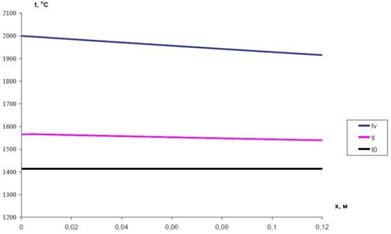
Fig. 10. Change in the temperature of flow of the gas phase (–tv) and the molten silicon (-tl) along the channel of the pyrolysis reactor.
Fig. 11. Change in the temperature of the flow of gas phase (-tvr) and molten silicon (-tlr) along the condenser (tsi_m - the melting point of silicon).
3. Investigation of 30 kW Laboratory-Scale Electric Arc Reactor
The 30 kW laboratory-scale unit is intended to be a simplified analogue of the 150 (300) kW pilot unit, and it should be used to model and optimise all the main assemblies [12].
A wide-range of thermal decomposition of monosilane can be provided by varying the operating parameters of the plasmatron (power input, plasma gas flow rate and monosilane consumption) (Fig. 12 a, b). The silicon melt flowing down over the wall of the pyrolysis reactor channel in operation of the reactor is separated into two parts. The first part flows down in the form of a film and cools in contact with atmosphere. The second part consists of the droplets, which are formed in a flow of the film and blown off by plasma. If these droplets in the form of granules get into the core of the jet, they fly away along it. If they move on the periphery, they are scattered near the reactor as glowing tracks shown in Fig. 12 b. As the silicon granules are in an atmosphere of oversaturated vapours, the vapour particles condense on the granule surfaces. The silicon vapour is carried away along the flow, where, while it cools down, its homogeneous condensation in the gas phase occurs to form silicon macro particles.
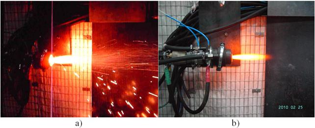
Fig. 12. Reactor of pyrolysis in operate: a – without monosilane; b – with monosilane.
Investigation of skull film in pyrolysis reactor channel. The 30 kW laboratory-scale plasma unit was used to investigate interaction of molten silicon with silicon skull both on the graphite base and reinforced with silicon nitride under the pyrolysis reactor conditions. The pyrolysis reactor wall is made from high-density graphite. At the beginning, feeding of the silicon powder in the nitrogen plasma was switched on for 10 min to produce a composite layer with silicon nitride on the working surface. As a result, a 1 mm thick coating with the composite structure of silicon nitride and silicon was formed on the internal wall of the pyrolysis reactor. After that, the monosilane was blown through the pyrolysis reactor channel to the argon-hydrogen plasma to provide its decomposition. The silicon vapours were deposited on the skull surface of the pyrolysis reactor channel to form a film-like flow of silicon. Under the effect of the plasma flow, the molten silicon film in the channel transformed into droplets, which flowed from the nozzle. The reactor was dismantled after being in operation for 3 hours. The graphite channel was cut along the axis to make sections of its different regions. The purpose of investigation of the sections and working surface of the used pyrolysis reactor was to study main principles of interaction of molten silicon of a composite structure (silicon nitride – silicon) and silicon with high-density graphite. Investigations were carried out by using "Philips" (The Netherlands) scanning electron microscope SEM-515 equipped with an energy-dispersive spectrometer of the "Link" system. The film-like flow of silicon in the graphite pyrolysis reactor channel in the nitrogen plasma atmosphere results in formation of plasma-chemical silicon nitride. This was confirmed by X-ray analysis, which was performed by using the DRON-UM1 instrument in Cuka radiation with graphite monochromator at a scanning pitch of 0.05°, time of exposure at a spot equal to 5 s, U = 5 kV, and I = 25 mA.
The analysis results are indicative of formation of a porous coating consisting of 12% Si3N4 of the a-phase, 42% Si3N4 of the b-phase and 46% silicon. Therefore, the flow of molten silicon in this case occurs in silicon, and at the optimal proportion of the phases the problem of wetting of the materials is eliminated. There is a wide range of conditions providing a stable equilibrium, at which the amount of silicon deposited from a vapour on the plasmatron and reactor channel surfaces is equal to the amount of silicon carried away in the form of droplets, this resulting in a stable flow of molten silicon over the silicon film. Thickness of this film remains constant. For example, at an initial diameter of the graphite channel of the pyrolysis reactor equal to 11 mm, thickness of the film is approximately 1 mm, i.e. the real working diameter of the channel becomes equal to approximately 9 mm. This value is approximate, because the surface of the channel is wavy as a result of a turbulent flow of molten silicon.
The skull film formed in the pyrolysis reactor channel under different operating conditions was comprehensively studied. A). Silicon film on graphite base. Different modes of the flow of molten silicon and different structures of the skull film may form in the pyrolysis reactor channel depending on the heat flow density, surface temperature and dynamic pressure at interface.
Different modes of the flow of molten silicon may form on the surface of the pyrolysis reactor channel: laminar, transient, fine-turbulent, coarse-turbulent, and droplet one.
Fig. 13 shows a panoramic view of the surface of the pyrolysis reactor channel in a region with the laminar flow (a) and turbulent flow (b).
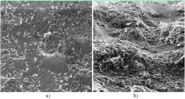
Fig. 13. A panoramic view of the surface of the pyrolysis reactor channel in a region with the laminar mode of the flow of molten silicon: a - (x500), b - the turbulent mode of the flow of molten silicon (x 600).
The turbulent mode of the flow of molten silicon transforms into the droplet one.
B). Silicon skull on silicon nitride base. The silicon nitride film was produced in the following way on the working surface of the pyrolysis reactor channel by plasma-chemical synthesis in the nitrogen plasma. The plasmatron and the pyrolysis reactor were switched on by using nitrogen as a plasma gas. After heating the graphite insert to 1500°C, the silicon powder was fed for 10 min. During this time a composite coating of silicon nitride with silicon, about 1 mm thick, formed on the working surface of the pyrolysis reactor channel. After that, the plasmatron and reactor were switched over to operation with the argon- hydrogen mixture as a plasma gas and monosilane as a working gas.
Consider the transverse section of the pyrolysis reactor channel with a silicon nitride coating and silicon skull film on it, which was in operation for 4 h (Fig. 14).
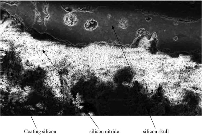
Fig. 14. Microsection of working surface of the pyrolysis reactor channel (x100).
Analysis of the processes occurring in the condensation reactor (Figs. 1) indicates to the following:
• the mode of operation of the plasmatron with decomposition of the monosilane at a level of 4 g/s provides the following distribution of condensation at the reactor exit – the amount of the ultradispersed powder carried away with gas is 0,5 g/s, and 3,5 g/s of this powder flows down to the melt from the walls. These figures are indicative of the fact that optimisation of the condensation reactor will provide a sufficiently high degree of transfer of silicon from the vapour phase into liquid;
• conditions of the turbulent flow of molten silicon over the surfaces of the pyrolysis and condensation reactors seem to be very close to each other, despite a substantial difference in temperatures and rates, which is proved by approximately identical sizes of the silicon droplets that are carried away;
• the reactor as a whole can have such a mode of operation, where the condensation reactor is combined with the granulator, i.e. the processes of condensation of the silicon vapour into a liquid film and transformation of flow of this film into the droplet one simultaneously take place on its working surface;
• size of the forming droplets in the first approximation obeys the general laws, and can be described by using the Weber criterion that relates the size to the rate of a relative flow, viscosity and surface tension, i.e. increase in the working temperature and velocity of gas in the near-wall layer leads to decrease in mean size of the droplets, and vice versa.
Further elaboration of the discovered effect, when the condensation reactor is combined with the granulator, i.e. where the processes of condensation of silicon vapours into a liquid film and transformation of flow of this film into the droplet one simultaneously take place on its working surface, leads to formation of a new concept of the condenser – granulator. Granulator of the laboratory-scale unit was developed and manufactured on the basis of this concept. A fragment of connection of the condensation reactor with a quartz tube (2000 mm long and 90 mm in internal diameter) for preliminary cooling of droplets is shown in Fig. 15. The quartz tube is hermetically fixed in a lid of the receiving water-cooled container. The flow of gas, such as nitrogen, hydrogen or water vapour, providing a shielding atmosphere and forced convective cooling of the molten silicon droplets, is fed via a separate line to the receiving container. In addition, this gas flow forms a gas-dynamic gate preventing penetration of the silicon vapours from gases that flow out from the condensation reactor to the zone of cooling of the molten silicon droplets. Fig. 15 shows operation of the granulator in a mode of formation of silicon droplets with a size of £ 2 mm.
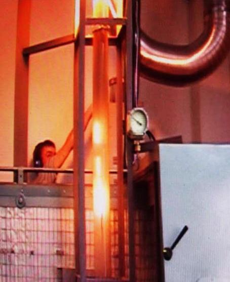
Fig. 15. Operation of the condensation reactor combined with the granulator.
4. Creation of the Pilot Setup for Industrial Processing of Monosilane into Silicon
Installation consists of the following modules:
1) Pyrolysis reactor with a condenser and heat exchanger assembly (the reactor);
2) Plasmatron;
3) Granulator, includes a fluidized bed unit, an intermediate holding tank and output holding tank;
4) Plasmatron power source includes thyristor processor rectifier, insulating transformer and an output choke;
5) Cooling water chiller;
6) Gas console;
7) Water console;
8) Control console;
9) The system of working gases of silane, hydrogen, argon and nitrogen;
10) The recycling system for the exhaust gases.
Technical characteristics of the pilot unit shown in table 2.
Table 2. Technical characteristics of the pilot unit.
| # | Parameter | Unit | Value |
| 1 | The greatest performance in terms of silicon | kg/h | 50 |
| 2 | Power consumption, no more than | kVA | 400 |
| 3 | Plasmatron power consumption | kW | 200 |
| 4 | Maximum monosilane flow rate | kg/h | 65,2 |
| 5 | Monosilane pressure | MPa | 0,5 |
| 6 | Hydrogen flow rate | kg/h | 5-20 |
| 7 | Hydrogen pressure | MPa | 0,5 |
| 8 | Argon flow rate | kg/h | 5-20 |
| 9 | Argon pressure | MPa | 0,5 |
| 10 | Nitrogen flow rate | kg/h | 5-20 |
| 11 | Nitrogen pressure | MPa | 0,3 |
| 12 | Excessive pressure in the reactor, no more than | MPa | 0,02-0,05 |
| 13 | Temperature of exhaust gases, no more than | °С | 200 |
| 14 | Cooling water flow | m3/h | 8,5 |
| 15 | Cooling water pressure | MPa | 0,3 |
| 16 | Cooling water temperature input – output difference | °С | 20 |
The plasmatron, a non-standard item, is a key element of the setup. This product is intended for an electric heating of argon/hydrogen mixture and obtaining the monosilane pyrolysis products. The product works as part of the installation for continuous production of silicon granules with specialized power source, gas and water consoles.
In a Fig. 16 a, b it is shown general view of the plasmatron connected with condenser.
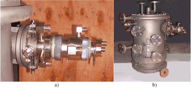
Fig. 16. General view of the plasmatron (a) with condenser (b).
The presence of liquid silicon and the high purity demands set the baseline for the reactor structure (pyrolysis reactor and vortex chamber as condenser). Constructive design of the pyrolysis reactor connected with a condenser channel is shown in a Fig. 17. Pyrolysis reactor shell is tightly attached in the cylindrical case of the condenser with a radial offset from its longitudinal axis so that its axial channel ensured a tangential inlet of the pyrolysis products into a working volume of the condenser cyclone chamber Fig. 1 a. The outer wall is covered with plasma sputtered coating of zirconium dioxide stabilized with yttrium oxide, with variable thickness of 0, 5 mm.
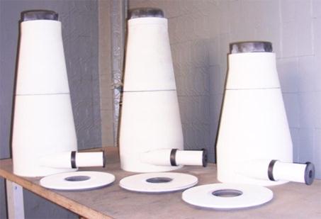
Fig. 17. Constructive design of the pyrolysis reactor connected with a condenser channel.
The lower flange of the condenser is tightly attached to cooler (Fig. 1 b) is a shell-and-tube heat exchanger of gas - water type in which the exhaust gases pass through the 180 tubes, 12 mm in diameter and 0.5 meters long, give up to 70 kW of thermal power and cool to a temperature of ≤ 200°C. The upper heatsink flange is firmly attached to the bottom flange of the condenser. The cylindrical cavity between the bottom wall of the condenser and the upper wall of the cooler form a silicon output node, where the streams of exhaust gases and liquid silicon are separated.
Reactor with coolant installed is done of three weldments: top lid, condenser and cooler - all are tightly connected. Plasmatron is tightly connected through the flanges to the pyrolysis reactor. Condenser and cooler contain combs for cooling water supply and discharge, thermocouples and sensors mountings nodes. At the lower flange of cooler there is bursting diaphragm pipe bend installed.
5. Results and Discussions
As proved by thermodynamic analysis, monosilane is an artificial formation, which decomposes into silicon and hydrogen at a temperature as low as the ambient temperature. Finally, the time of decomposition is determined by the temperature. Under the conditions of interest, the time of decomposition, e.g. at 1800°C, is 2×10⁻⁵ s. At a plasma velocity of about 1000 m/s, decomposition of monosilane will take place at a distance of 2 cm. Therefore, decomposition of monosilane is an optimisation parameter, rather than a limiting factor for selection of dimensions of the reactor. Consumption of energy for plasma pyrolysis of monosilane is an important parameter of the process. Using the results characterising the amount of processed monosilane (produced silicon) and time of dwelling in the reaction zone, together with the calculated values of the amount of monosilane decomposed during this time, makes it possible to evaluate in the first approximation the efficiency of the pyrolysis process conducted at different temperatures in the reaction zone. For example, at useful plasmatron power W = 100 kW, volume ratio VAr/VH2 = 0.2/0.8 (weight ratio g = 0.6667) and reaction zone length L = 0.06 m, we obtain (Fig. 9) that
minQSi_sp_kin = 1.69 kW×h/kg Si,
GSi_kin = 50 kg/h Si,
tr_opt = 1517°C,
Qpl_sp_opt = 3.17 kW×h/nm3, and
tpl_opt = 3699°C.
The heat consumed for pyrolysis of monosilane is partially returned in condensation of silicon vapours. This circumstance is a useful factor to make the silicon melt flow down over the reactor walls. To eliminate diffusion of admixtures from the reactor material into the silicon melt, it is advisable to perform the process in the skull mode, i.e. by removing heat from the reactor walls. In this case, the silicon melt will flow down over the solid silicon, and will not enter into contact with the reactor material.
The given technology for continuous production of silicon granules from monosilane through the liquid phase in one apparatus is based on a wide variety of interrelated physical processes. The comprehensive experimental and mathematical modelling performed in this study give a sufficiently clear idea of the technological cycle as a whole.
The important circumstance consists in peculiarities of heating of hydrogen to high temperatures. They are associated with thermal-physical properties of hydrogen in the dissociation region, including intensive growth of enthalpy and dramatic increase of thermal conductivity, followed by its drop and maximum at 3800 K. Heat capacity behaves identically. At the weight-average temperatures above 3500 K, the abnormally high thermal conductivity of hydrogen begins to play the leading role in heat exchange. The above peculiarities of thermal-physical properties of hydrogen result in an increased density of the heat flow into the electrode at a temperature of about 3800 K, which may amount to 2 kW/cm2 or more, i.e. be close to a limiting value of about 5 kW/cm2 for the actually existing cooling systems. It is obvious that at such a high heat load an important role in maintaining performance of the plasmatron will be played by selection of the rational modes of the plasma flow, namely: before and after the dissociation peak, and optimisation of its cooling system. The important element of a high-temperature path is the pyrolysis reactor channel. In fact, pyrolysis of monosilane to produce silicon aerosol will take place here. The efficient operation of the plasma-chemical reactor, complete and reasonable utilisation of its volume at the minimal losses of raw materials and energy can be achieved due to rapid and efficient mixing of the raw materials and heat carrier. As proved by our investigations, the most successful design is that of the reactor with hot walls, where the heat losses are minimised. As in the laboratory reactor the gas temperature is much in excess of the wall temperature (it is at a level of the silicon melting point equal to 1400 ± 100°C), the heat should be removed from the working surface, and the heat removal intensity should be decreased along the length of the reactor channel. The law of drop of the heat removal intensity is calculated from mathematical models and is checked experimentally. The mean density of the heat flow through walls of the pyrolysis reactor channel is 1 kW/cm2. Based on the experimental and calculated twofold temperature drop in the first approximation, it is necessary to ensure an adequate distribution of heat transfer parameters along the pyrolysis reactor channel at entrance to the reactor at a level of 2 kW/cm2, and their drop at the exit equal to 0.5 kW/cm2. This provides maintaining a temperature of the surface of the high-density graphite channel wall at a level of 1400°C along its length. Heat transfer from plasma to the channel wall in the inlet part of the channel is determined mostly by the turbulent heat exchange processes. The heat and mass exchange processes due to condensation of the silicon vapours and liquid film flow are added to the turbulent heat exchange as it moves downstream along the channel. The pyrolysis reactor has a unified cooling system. So, the contradictory requirement to cooling of its flow-through part consists particularly in this fact. The contradiction can be resolved by using the so-called "thermal lens", where the temperature resistance between the working wall of the flow-through part of the pyrolysis reactor channel and external water-cooled wall increases towards the channel outlet. This can be achieved by combining materials with different thermal conductivities at the same total wall thickness. Here, the technical problem consists in providing a tight contact over the entire surface and absence of any defects in order to avoid uncontrollable local warping.
Upon achieving the optimal temperature mode, formation of the skull and working wall material becomes most important. Analysis of numerous specimens cut out from the used pyrolysis reactor channel gives a sufficiently clear idea of the processes occurring on the surface of its flow-through part. Silicon is condensed during operation on the pyrolysis reactor surface to form a solid skull film 1.0-1.5 mm thick. The liquid silicon film flows over the skull surface in the turbulent mode. Thickness of the liquid silicon film remains almost unchanged during the flow. Excessive silicon condensed on the surface coagulates into droplets, which are continuously blown out by the gas flow, the average size of the droplets in the first approximation correlating with the Weber criterion. Increase in the wall and gas temperature leads to decrease in the average size of the droplets, and vice versa. That is, the key role is played by surface tension, viscosity of the melt and dynamic pressure of the blowing gas. The following was established concerning formation of the skull. Molten silicon does not wet the silicon nitride surface and, most likely, is kept only due to the mechanical adhesion forces. The molten silicon film flowing over the silicon nitride surface always contains discontinuities. Therefore, the silicon nitride base material will always have contact with the gas phase. As the gas phase temperature (1600 - 2000°C) is higher than the working temperature of silicon nitride (1300 - 1500°C), this material is unsuitable to provide the continuous process of production of silicon through the liquid phase. It is notable that a composite structure of crystals of silicon nitride, mainly the b-phase, and silicon forms in the process of plasma-chemical synthesis of silicon nitride. Moreover, a strong pore- and defect-free adhesive bond, which is not destructed during operation, forms between them. This is an important circumstance, which points the way to solving the problem. It is apparent that all the working surfaces of the flow-through part of the pyrolysis and condensation channels should be skull-forming. Thickness of the wall material of the flow-through part of the reactor channel is chosen on the basis of providing mechanical strength and 50-100°C decrease of temperature to maintain the stable skull. Most suitable for this purpose is a composite material containing stable compounds at a temperature of up to 1500°C, which are neutral with regard to silicon. This should be a porous frame of carboxynitride ceramics impregnated with silicon in such a way that a variable structure is produced as a result. The internal working surface should change into pure silicon. And the surface layer of pure silicon will act as a skull. Judging from public literature data, the b-phase of Si3N4 can be used as a frame material component, as it is more resistant to the silicon melt that the a-phase. Of notice is a wide scatter of the available data on the contact angle of wetting of silicon nitride with molten silicon. It ranges from 10 to 100o. This can be explained by a considerable scatter of properties of the surface (defects, impurities etc.) depending on the production method and ambient atmosphere. In any case, to select materials and a technology for manufacture of wall of the flow-through part of the reactor, one should rely on the experience gained from operation of crucibles with molten silicon. The temperature mode of heating of the reactor should be selected so that temperature of the internal wall is not in excess of the melting point of silicon, i.e. 1300-1350°C. The reactor being heated up, monosilane is fed for pyrolysis. Due to the extra heat of pyrolysis and condensation of vapours, the walls are heated up to a melting point of silicon, which is 1410°C, and the condensed silicon vapours in the form of the liquid film flow down over the solid silicon base. This auto-temperature mode is provided by the balance of heat flows in the entire flow-through part of the reactor.
Exit of the pyrolysis reactor is an inlet branch tube of the cyclone-type vortex condenser. In fact, it is an inertia trap, wherein precipitation of silicon from vapours into the liquid on the wall occurs mostly under the effect of the centrifugal force, which is generated by rotation of the gas-dispersed flow inside the apparatus. The two-phase flow of hydrogen with the ultradispersed silicon particles (as a result of homogeneous condensation) enters the condenser via a tangential channel of the pyrolysis reactor, where, by acquiring a rotational motion, it lowers down in a helical fashion along the internal walls of the condenser cylinder and cone. Because of the rotational motion of the two-phase flow at a high circumferential speed of 400-660 m/s, a decreased pressure is formed in the central part of the cyclone, and light hydrogen is concentrated here. The heavier silicon particles are pressed to the wall by the centrifugal forces. 3D modelling of the separation process under such conditions indicates that it is theoretically feasible that 100% of all silicon particles will reach the cyclone surface. The question that remains open is a condensation coefficient, which is a ratio of the quantity of silicon particles entrapped by the surface to their total quantity in aerosol. Investigations with the laboratory reactor show that this coefficient is very high without optimisation of the process. Totally 8-10% of silicon vapours went out with the exhaust gas. An important natural property of the molten silicon flow over the surface of the pyrolysis reactor and condenser is a continuous transformation of the film-like flow into the droplet one. The droplets formed in the condenser roll down under the effect of the gravity force and gas flow. This creates conditions for combining two processes, i.e. condensation of silicon vapours and production of granules, into one technological operation, thus leading to a substantial reduction in the time of contact of molten silicon with the hot walls (this time is no more than a few seconds) and, therefore, decreasing its contamination.
The discovered phenomenon of rapid coalescence of the liquid silicon film into droplets opens up the technical possibility for manufacture of a granulator on this base. Estimation of the rate of cooling of the silicon droplets shows that natural cooling is time-consuming. Therefore, it is reasonable to conduct this process in the fluidised bed. The main commercial equipment available for production of granulated products, i.e. granulators, is characterised by a wide range of designs and methods used to perform the granulation process. The use of the boiling-bed granulators is most expedient for manufacture of granulated products from the melts at low- and medium-capacity enterprises. Their advantage is that the heat and mass transfer processes in the boiling bed are more intensive than in other types of the granulation equipment. Therefore, such apparatuses have smaller dimensions than similar granulation apparatuses of other types. The boiling-bed apparatuses have simpler design.
6. Conclusions
1. Integrated mathematical and full-scale modelling of the equipment and processes for production and condensation of silicon vapours on a hot wall of different materials to form a skull, provide a flow of molten silicon, produce silicon droplets and cool them was carried out.
2. As proved by the investigations conducted, there are no scientific or technical bans on practical implementation of the technology for continuous production of granulated silicon in the plasma pyrolysis apparatus.
3. Adequate mathematical description of the process and equipment, having a different degree of accuracy, was obtained, thus allowing an engineering development of the pilot unit with a productivity of 50 kg/h.
4. The considered technology for continuous production of silicon granules from monosilane through the liquid phase in one apparatus is based on a wide variety of interrelated complicated physical processes. Therefore, the results obtained should be regarded as preliminary. Verification and optimisation of elements of the unit and process parameters will be required to bring the process up to the maximal efficiency.
References


