Metallurgical Investigation of Incidence to Cracked Round Corner Square Bloom (RCS) of Wheel and Axle Grade Steel
P. Saravanan*, Bhawna Khalkho, S. Srikanth, Atul Saxena
Research and Development Centre for Iron and Steel, Steel Authority of India Limited (SAIL), Ranchi, India
Email address

(P. Saravanan)
*Corresponding author
Citation
P. Saravanan, Bhawna Khalkho, S. Srikanth, Atul Saxena. Metallurgical Investigation of Incidence to Cracked Round Corner Square Bloom (RCS) of Wheel and Axle Grade Steel. Engineering and Technology. Vol. 3, No. 5, 2016, pp. 93-99.
Abstract
The defective Wheel and Axle (WAP) grade of Round Corner Square (RCS) bloom steel sample with surface cracking was investigated concurrently using optical emission spectroscopy (OES) and light optical microscopy coupled with scanning electron microscopy. The incidence of extensive decarburization and grain coarsening at the crack surfaces, the presence of fragmented oxide scale debris within the cracks and the occurrence of massive subsurface entrapments of manganese silicate inclusions associated with the crack like features in the WAP grade of RCS bloom sample clearly indicate the pre-existence of these defects in the input ingots and point to their possible origin in steel making and ingot casting.
Keywords
Round Corner Square (RCS) Bloom, Wheel and Axle (WAP) Grade Steel for Railways, Non-metallic Inclusion, Decarburization, SEM-EDAX
1. Introduction
Steel contains varying amount of impurities like silicon, phosphorous, sulfur and some traces of manganese and copper called as metallic impurities. Due to various thermodynamic conditions during melting and solidification of steels, many non metallic compounds are formed and are referred as inclusions. The formation of non metallic inclusions is linked to the admixtures in the alloy, phase composition, structure and morphology, which in turn depends on metallurgical process. The distribution of non-metallic inclusions in steel and their quality are determined by various factors, including charge quality, process regime, furnace type and out-of-furnace processing [1-7]. Oxidized or non-metallic impurities, mainly oxides, sulphides, and silicates of iron and manganese, are also frequently found in the steel. Sulfur, however, is sometimes classified as a non-metallic impurity [8-10]. Non-metallic impurities are compound materials embedded inside steel during manufacturing process [11]. There is a sharp distinction between the metallic and non-metallic impurities, the former with the exception with the sulfur, forming true alloys with the contaminated metal, the later being merely inclusions, their union with the metal being purely mechanical [12]. As already mentioned steel generally contains varying amount of non-metallic, oxidized impurities frequently called slag "enclosures" or "inclusions", [12] while Hibbard proposed for them the name of "sonims" for this class of impurities, in which "so" stands for solid, "n" for non-metallic and "ims" for impurities [13]. The slag mainly consists of iron and manganese oxides and silicates although sulphides of iron and manganese are generally considered also as slag enclosures. These impurities are mainly derived (a) from the retention by the metal of the minute particle of the slag formed during the manufacture process. (b) from small species of refractory material detached from the furnace and ladle linings and (c) reaction products resulting from the introduction of recarburizers or other additions. According to Hibbard, slag enclosure formation is due almost entirely to the "washing" action of the additions, principally of manganese, in combining with oxides, sulphides and silicates which are present in the steel at the end of the melting process before the manganese is added since enclosures rich in manganese must necessarily have formed after the addition of that constituent. Stead [13] on the other hand express the belief that silicate enclosures at all events are due to oxidation of manganese and silicon occurring during the passage of the molten steel through the air in passing from the ladle into the mould. In the case of iron oxide it seems probable that the small particles of it remain in suspension in the molten steel forming as many as small inclusions after solidification, while other portion, dissolved in the liquid metal, is in part precipitated during solidification. In Rosenhain’s opinion [13], it is not proven that the sulphides and silicates are not soluble in molten steel. After solidification, the association between the slag enclosures and the molten steel remains a purely mechanical one; they commonly occur as rounded or elongated particles embedded in the metal.
Silicates are the biggest group among the non-metallic inclusions which form separate phases [14]. These manganese or iron silicates are darker as compared to the sulphides and because of their relative brittleness are frequently broken and torn by the forging operation. They are the cause for dangerous and serious material defects such as brittleness and wide variety of crack formations. However, some of these inclusions can also have a beneficial effect on steel properties by nucleating acicular ferrite during the austenite to ferrite phase transformation especially in low carbon steels [15-16].
One such cracking was observed in round corner square (RCS) Bloom (a semi-finished casting product) of Wheel and Axel (WAP) grade steel used for rail wheel during final processing. The RCS bloom sample was metallurgically investigated to know genesis of cracking.
2. Materials and Methods
The chemical composition of round corner square (RCS) bloom was analyzed using a Bruker Q8 Magellan Optical Emission Spectroscopy (OES). It was performed on the cross-sectional surface of the bloom sample. The defective bloom sample was initially subjected to visual examination under low magnification (~20X) using Olympus GX-71 inverted metallurgical Optical Microscopy and the flawed sample surfaces were photographed. The defective surfaces associated with crack was cross-sectional examined under Scanning Electron Microscopy (SEM) coupled with Energy Dispersive Spectrometry (EDS), Zeiss Model EVO_MA 10, in both polished as well as in as etched condition.
Table 1. Sample details of Round Corner Square (RCS) Bloom sample receiver from Alloy Steel Plant (ASP).
| Grade | Sample type | Heat No. | Size/ dimension |
| WAP -1/95 | RCS Bloom | 3-2320 | Irregular |
3. Results
3.1. Visual Examination
Fig. 1 shows the photographs of defective bloom samples received from Alloy Steel Plant (ASP) for investigation. Visual appearance of surface cracks in WAP bloom samples. The sample details are presented in Table 1.
3.2. Chemical Analysis
Table 2 gives the chemical composition of the defective bloom sample determined using optical emission spectroscopy (OES). From the analysis it can be said that the steel is simply medium carbon steel comprising of alloying elements such as Si, Mn, Al and traces of S and P.
Table 2. Composition (wt %) of failed sample.
| C | Mn | Si | S | P | Al |
| 0.36 | 0.79 | 0.36 | 0.007 | 0.01 | 0.026 |
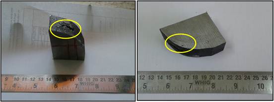
Fig. 1. Visual appearance of the surface crack in WAP bloom sample (Sample portions subjected to optical microscopy and SEM-EDS observation and analyses are circled).
3.3. Optical Microscopic Analysis
Fig. 2 and Fig. 3 shows optical micrograph of the cracked bloom sample in as-polished unetched condition depicting branched crack filled with fragmented oxide scales and entrapments. Fig. 4 show magnified micrographs of the cracked bloom sample in as-etched condition. The sample was etched using 2% nital solution. This clearly shows extensive decarburization and grain coarsening at the crack surfaces along with associated inclusions.
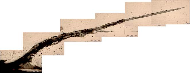
Fig. 2. Light optical micrograph of the cracked bloom sample showing a curvilinear, long, tapering crack extending from sample surface to interior replete with fragmented oxide scale debris.
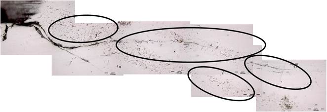
Fig. 3. Light optical micrograph of the cracked bloom sample showing a fine, curvilinear, tapering and branched crack filled with fragmented oxide scales and a preponderance of subsurface entrapments/ inclusions (circled).
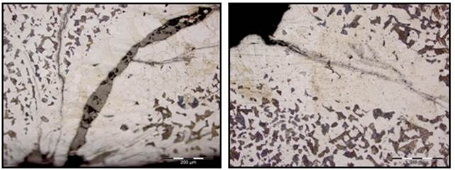
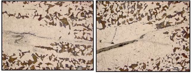
Fig. 4. Light optical micrographs of the bloom sample showing various magnified views of the crack with extensive decarburization and evidences of grain coarsening adjacent to the crack surfaces along with associated entrapments/ inclusions in as-etched condition.
3.4. Electron Microscopic Analysis
Fig. 5 show Secondary electron micrographs of cracked bloom specimen in as-polished (unetched) condition. Fig. 6 shows the magnified secondary electron image of the crack in as-polished (unetched) condition and Table 3 shows the corresponding electron Dispersive Spectroscopy (EDAX) analysis (all elements analysis in wt %) of the SEM micrograph Fig. 6 in as-polished (unetched) condition at different location of the crack confirming the presence of fragmented iron oxide debris and inclusions/entrapments.
Fig. 7 show Secondary electron micrographs of cracked bloom specimen in as-etched condition depicting magnified views of the crack with extensive decarburization and grain coarsening adjacent to the crack surfaces along with entrapments. Fig. 8 shows SEM image of EDAX analysis (Table 4) in as-etched condition of the crack confirming manganese silicate inclusion within the cracks and extensive decarburization and evidences of grain coarsening. This entrapment/inclusion in steel is mostly from steel making origin.
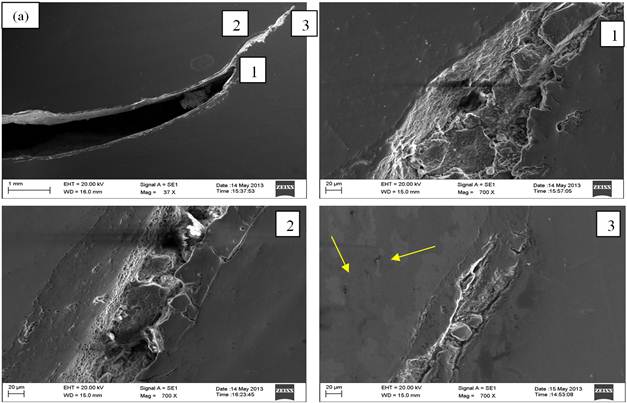
Fig. 5. Secondary electron images of the (a) crack RCS bloom sample and (1, 2 and 3) magnified image of crack [image of (a)] exhibiting crack filled with fragmented oxide scale debris and associated with massive entrapment in as-polished unetched condition.
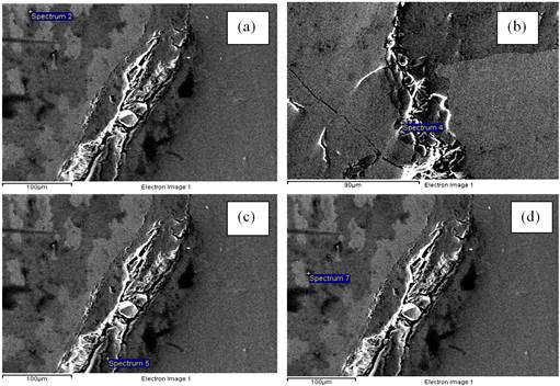
Fig. 6. SEM analysis performed at various locations at vicinity of the crack in as-polished unetched condition.
Table 3. EDAX analysis of corresponding SEM micrographs of Fig. 6 namely (a) to (d) confirming the presence of fragmented iron-oxide scales and entrapments/inclusions in as-polished unetched condition. (All analysis is in wt %).
| Locations | C | O | Al | Si | S | Fe | Mn |
| a | 2.39 | 20.16 | --- | 1.22 | --- | 76.22 | --- |
| b | --- | 18.47 | --- | --- | -- | 80.39 | 1.14 |
| c | 7.66 | --- | --- | 77.67 | | 14.67 | --- |
| d | 7.86 | 5.13 | 6.05 | 19.70 | 1.57 | 59.68 | --- |
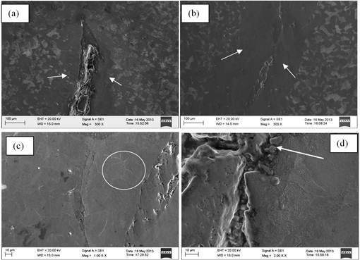
Fig. 7. Secondary electron images of the cracked bloom sample showing various magnified views of the crack with (a and b) extensive decarburization and (c) evidences of grain coarsening adjacent to the crack surfaces along with associated (d) entrapments of oxide scales and inclusion.
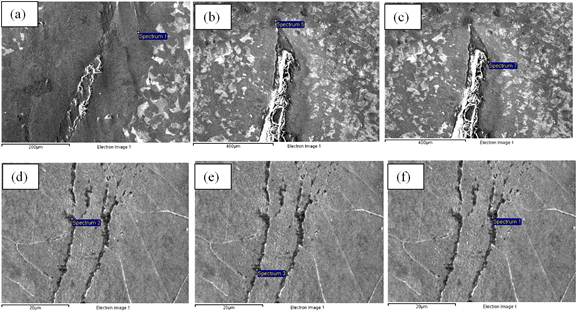
Fig. 8. Image of SEM and EDAX analysis performed at various locations at the vicinity of crack defects showing extensive decarburization and evidences of grain coarsening at the crack surfaces in as-etched condition.
Table 4. Shows the EDS analysis of the SEM micrographs of Fig. 8 namely (a) to (d) confirming the presence of fragmented oxide scales and massive entrapments of manganese silicate inclusion within the cracks in as-etched condition. (Analysis are in wt.%).
| Locations | C | O | Mn | Si | Fe | Cl |
| a | 0.19 | 20.18 | --- | --- | 77.23 | --- |
| b | 0.02 | 23.50 | --- | --- | 72.17 | 4.35 |
| c | 0.16 | --- | 1.06 | | 98.37 | --- |
| d | 1.39 | 25.61 | 2.86 | 9.68 | 60.46 | --- |
| e | 1.63 | 22.20 | 2.35 | 9.73 | 64.09 | --- |
| f | 1.13 | 21.26 | 1.87 | 8.94 | 66.79 | --- |
4. Defect Genesis
The round corner square bloom (RCS Bloom) is processed through ingot casting route with ingot dimensions of 610mm2 cross-section at top, 500mm2 cross-section at bottom and 1.6m in length. The ingots are reheated to temperature of about 1270-1280°C and transferred to the blooming mill where the ingots are rolled to the semi-finished product as blooms. The blooms are finished to 80/100/200/340 mm dimensions with the finishing temperature of about 900°C.
During solidification of the liquid steel, non-metallic inclusion such as silicates with admixture of manganese forms from the solution [17]. Since manganese silicate inclusion having less solubility, it rejects out from the solution and weakens the grain boundary. This causes liquid-metal embrittlement which results in brittleness of the bloom samples. At the room temperature this inclusion is brittle but increasingly deformable at the rolling temperature (~1150°C). For rolling, the input temperature should be above 1150°C. If the ingots are rolled below 1150°C then manganese silicate inclusion causes cracks influencing the quality of RCS bloom. Generally crack originates from these types of non metallic inclusion only when rolling is carried out below 1150°C and with heavier reduction (~70-80%).
During ingot casting if temperature exceeds 1540°C, oxygen gets pick up from the atmosphere and forms a thick oxide layer at the ingot surface. If there is a pre-existing crack at the surface, the oxide formed at the surface progresses into the crack and thereby filling the crack with oxide scales. Also the area near to the vicinity of crack gets exposed to the elevated temperature. The carbon near to the crack areas gets depleted and combines with oxide to form carbon dioxide as seen from Ellingham diagram [18-19]. This depletion of carbon from the steel matrix is known as decarburization effect. Due to decarburization, grain coarsening occurs near to the crack thereby decreasing the strength and ductility [20-24]. Further rolling of ingots will lead to a propagation of crack along grain coarsened area.
Hence it can be concluded that prevalence of sub-surface entrapments of manganese silicates inclusion, decarburization and later rolling at low temperature (~1150°C) with higher reduction may be genesis of failure of the RCS bloom.
5. Conclusion
The defective WAP grade bloom sample with surface cracking was investigated concurrently using OES and light optical microscopy coupled with scanning electron microscopy. The detailed investigation provided the following conclusive revelations:
(a) Preponderance of sub-surface entrapments of manganese silicates inclusion in the ingot serves as the source of crack propagation during rolling.
(b) Presence of fragmented oxide scale debris within the cracks results due to depletion of carbon from steel matrix.
(c) Extensive decarburization and grain coarsening at the crack vicinity due to high temperature exposure leads to faster crack propagation.
References
- Lipinski T., Wach A., (2015) Dimensional Structure of Non-Metallic Inclusions in High-Grade Medium Carbon Steel Melted in an Electric Furnace and Subjected to Desulfurization. Solid State Phenomena Volume 223: 46-53.
- Himemiya T., Wolczynski W., (2002) Prediction of Solidification Path and Solute Redistribution of an Iron-based Multi-component Alloy Considering Solute Diffusion in the Solid Materials. Transactions of the Japan Institute of Metals Volume 43: 2890-2896.
- Murakami Y., Kodama S., Konuma S., (1989) Quantitative evaluation of effects of non-metallic inclusions on fatigue strength of high strength steels, I: basic fatigue mechanism and fatigue fracture stress and the size and location of non-metallic inclusions. Int J Fatigue Volume 11 (5): 291-298.
- Park J. S., Park J. H., (2014) Effect of Slag Composition on the Concentration of Al2O3 in the Inclusions in Si-Mn-killed Steel. Metallurgical and Materials Transactions Volume: B 45B: 953-960.
- Hatfield, W. H. and Giles, G. W., (1940) Non-metallic Inclusions in steel Quantitative Evaluation-Part-I. Journal of the Iron and Steel Institute Volume 142: 237-276.
- Gulyakov V. S., Vusikhis A. S., Kudinov D. Z. (2012) Nonmetallic Oxide Inclusions and Oxygen in the Vacuum Jet Refining of Steel. Steel in Translation Volume: 42 (11): 781-783.
- Lipinski T, The influence of the distribution of nonmetallic inclusion on the fatigue strength coefficient of high purity steels (2015) Journal of Achievement in Materials and manufacturing Engineering, Volume 69: 18-25.
- Sheir, Jarman, Burstein, (2009) Non metallic Impurities, In: Richardson Tony J. A., Shreir’s Corrosion, 4Eds, Manchester: Elsevier Science, 257.
- D. Krewerth, T. Lippmann, A. Weidner, H. Biermann (2016) Influence of non-metallic inclusions on fatigue life in the very high cycle fatigue regime.International Journal of FatigueVolume: 84: 40-52.
- Niclas Anmark, Andrey Karasev and Par Goran Jonsson (2015) The Effect of Different Non-Metallic Inclusions on the Machinability of Steels. Materials Volume: 8, 751-783.
- Jian-hua LIU, Chang-ling ZHUANG, Xiao-ning CUI, Guo-xuan WANG, Quan-de GAO, Yan YANG (2014) Inclusion Distribution in Ingots Investigated by Dissection.Journal of Iron and Steel Research, InternationalVolume 21: 660-665.
- Hibbard Henry D., (1919) Present knowledge concerning non-metallic impurities of steel (sonims). Iron Age Volume 103: 1427-1429.
- Sauveur and Boylston , (1918) Impurities In Steel, In: Albert Sauveur, The Metallography and heat treatment of iron and Steel, 2 Eds., USA: Cambridge, Mass, 143.
- Martin Gagne, Eric Thibault, (1999) Control of inclusion characteristics in direct cast steel billets. Canadian Metallurgical Quarterly Volume 38: 311-321.
- R. Kiessling N. Lange, (1976) Non-metallic inclusions in steel. The Metal Society Volume 55: 50-110.
- J.-H Shim, Y.-J Oh, J.-Y Suh, Y. W Cho, J.-D Shim, J.-S Byun, D. N Lee, (2001) Ferrite nucleation potency of non-metallic inclusion in medium carbon steels. Acta Materialia Volume 49: 2115-2122.
- T. Lipinski, A. Wach (2010) The share of non-metallic inclusions in high-grade steel for machine parts. Archives Of Foundry Engineering Volume 10: 45-48.
- J. H. E. Jeffes (2001) Ellingham Diagrams. Encyclopedia of Materials: Science and Technology (Second Edition): 2751-2753.
- K. Ishizaki (1990) Phase diagrams under high total gas pressures- Ellingham Diagrams for hot isostatic press processes. Acta Metallurgica et Materialia Volume 38: 2059-2066.
- George F. Vander Voort (2015) Understanding and Measuring Decarburization. Advanced Materials and Processes Volume 9: 22-27.
- J. K. Stanley, (1943) Steel Carburization and Decarburization – A Theoretical Analysis,. Iron Age Volume 151: 31-39 and 49-55.
- F. E. Purkert (1982) Prevention of Decarburization in Annealing of High Carbon Steel. J. Heat Treating Volume 2: 225-231.
- E. Schuermann (1974) Decarburization and Scale Formation. Wire Journal Volume 7: 155-164.
- P. Saravanan, Gadadhar Sahoo, S. Srikanth, K. Ravi, (2011) Failure Analysis of Radiant Tube Burners in Continuous Annealing Line (CAL) of an Integrated Steel Plant. Journal of Failure Analysis and prevention Volume 11: 286–292.


