| 1. | ||
| 2. | ||
| 3. | ||
| 4. | ||
| 5. | ||
Structural-Parametric Model Electromagnetoelastic Actuator Nano- and Microdisplacement for Precision Engineering
Sergey Mikhailovich Afonin
Department of Intellectual Technical Systems, National Research University of Electronic Technology (MIET), Moscow, Russia
Email address

Citation
Sergey Mikhailovich Afonin. Structural-Parametric Model Electromagnetoelastic Actuator Nano- and Microdisplacement for Precision Engineering. Engineering and Technology. Vol. 3, No. 6, 2016, pp. 110-119.
Abstract
Structural-parametric model, parametric structural schematic diagram, transfer functions of electromagnetoelastic actuator nano- and microdisplacement for precision engineering are obtained. Effects of geometric and physical parameters of electromagnetoelastic actuators and external load on its dynamic characteristics are determined. For calculation of precision systems with piezoactuators the parametric structural schematic diagram and the transfer functions of piezoactuators are obtained. A generalized parametric structural schematic diagram and transfer functions of the piezoactuators are constructed.
Keywords
Electromagnetoelastic Actuators, Structural-Parametric Model, Piezoactuator, Deformation, Parametric Structural Schematic Diagrams, Nano- and Microdisplacement, Transfer Functions
1. Introduction
For precision engineering, nanotechnology, electronic engineering, microelectronics, nanobiology, power engineering, astronomy, antennas satellite telescopes and adaptive optics are promising the electromechanical actuators based on electromagnetoelasticity (piezoelectric, piezomagnetic, electrostriction, and magnetostriction effects). Piezoactuator - piezomechanical device intended for actuation of mechanisms, systems or management based on the piezoelectric effect, converts electrical signals into mechanical movement or force. Piezoactuators are used in the majority of scanning tunneling microscopes (STMs), atomic force microscopes (AFMs) [1-16].
In the present paper is solving the problem of building the structural parametric model of the electromagnetoelastic actuator nano- and microdisplacement in contrast solving its electrical equivalent circuit [5-7]. Equivalent circuits of the piezoelectric transducers are designed for calculation of piezoelectric transmitters and receivers. By solving the wave equation with allowance methods of mathematical physics for the corresponding equation of electromagnetoelasticity, the boundary conditions on loaded working surfaces of actuators, and the strains along the coordinate axes, it is possible to construct a structural-parametric model of the actuator.
The transfer functions and the parametric structural schematic diagrams of the actuators are obtained from a set of equations describing the corresponding structural-parametric model [17-30].
2. The Structural-Parametric Model of the Electromagnetoelastic Actuator
For the piezoactuator its deformation corresponds to stressed state. If the mechanical stress ![]() is created in the piezoelectric element, the deformation
is created in the piezoelectric element, the deformation ![]() is formed in it. There are six stress components
is formed in it. There are six stress components ![]() ,
, ![]() ,
, ![]() ,
, ![]() ,
, ![]() ,
, ![]() , the components
, the components ![]() -
- ![]() are related to extension-compression stresses,
are related to extension-compression stresses, ![]() -
- ![]() to shear stresses.
to shear stresses.
The matrix state equations [7] connecting the electric and elastic variables for polarized ceramics have the form
![]() , (1)
, (1)
![]() , (2)
, (2)
where the first equation describes the direct piezoelectric effect, and the second - the inverse piezoelectric effect; ![]() is the column matrix of electric induction along the coordinate axes;
is the column matrix of electric induction along the coordinate axes; ![]() is the column matrix of relative deformations;
is the column matrix of relative deformations; ![]() is the column matrix of mechanical stresses;
is the column matrix of mechanical stresses; ![]() is the column matrix of electric field strength along the coordinate axes;
is the column matrix of electric field strength along the coordinate axes; ![]() is the dielectric permeability matrix for T = const;
is the dielectric permeability matrix for T = const; ![]() is the elastic compliance matrix for
is the elastic compliance matrix for ![]() ;
; ![]() is the transposed matrix of the piezoelectric modules. In polarized ceramics PZT there are five independent components
is the transposed matrix of the piezoelectric modules. In polarized ceramics PZT there are five independent components ![]() ,
, ![]() ,
, ![]() ,
, ![]() ,
, ![]() in the elastic compliance matrix for polarized piezoelectric ceramics, three independent components of the piezoelectric modules
in the elastic compliance matrix for polarized piezoelectric ceramics, three independent components of the piezoelectric modules ![]() ,
, ![]() ,
, ![]() in the transposed matrix of the piezoelectric modules and three independent components of the dielectric constants
in the transposed matrix of the piezoelectric modules and three independent components of the dielectric constants ![]() ,
, ![]() ,
, ![]() in the matrix of dielectric constants.
in the matrix of dielectric constants.
The direction of the polarization axis Р, i.e., the direction along which polarization was performed, is usually taken as the direction of axis 3 for the longitudinal and transverse piezoelectric effects.
The generalized electromagnetoelasticity equation of the actuator [7] has the form
![]() , (3)
, (3)
where ![]() is the relative deformation along the axis i, E is the electric field strength, H is the magnetic field strength,
is the relative deformation along the axis i, E is the electric field strength, H is the magnetic field strength, ![]() is the temperature,
is the temperature, ![]() is the elastic compliance for
is the elastic compliance for ![]() ,
, ![]() ,
, ![]() ,
, ![]() is the mechanical stress along the axis j,
is the mechanical stress along the axis j, ![]() is the piezomodule, i.e., the partial derivative of the relative deformation with respect to the electric field strength for constant magnetic field strength and temperature, i.e., for
is the piezomodule, i.e., the partial derivative of the relative deformation with respect to the electric field strength for constant magnetic field strength and temperature, i.e., for ![]() ,
, ![]() ,
, ![]() is the electric field strength along the axis m,
is the electric field strength along the axis m, ![]() is the magnetostriction coefficient,
is the magnetostriction coefficient, ![]() is the magnetic field strength along the axis m,
is the magnetic field strength along the axis m, ![]() is the coefficient of thermal expansion,
is the coefficient of thermal expansion, ![]() is deviation of the temperature
is deviation of the temperature ![]() from the value
from the value ![]() , i = 1, 2, …, 6, j = 1, 2, …, 6, m = 1, 2, 3.
, i = 1, 2, …, 6, j = 1, 2, …, 6, m = 1, 2, 3.
For the electric and magnetic fields acting on the electromagnetoelastic actuator separately, we have [2,7,9]
the equation of inverse piezoelectric effect:
for the longitudinal deformation when the electric field along axis 3 causes deformation along axis 3
![]() , (4)
, (4)
for the transverse deformation when the electric field along axis 3 causes deformation along axis 1
![]() , (5)
, (5)
for the shift deformation when the electric field along axis 1 causes deformation in the plane perpendicular to this axis
![]() , (6)
, (6)
the equation of magnetostriction:
for the longitudinal deformation when the magnetic field along axis 3 causes deformation along axis 3
![]() , (7)
, (7)
for the transverse deformation when the magnetic field along axis 3 causes deformation along axis 1
![]() , (8)
, (8)
for the shift deformation when the magnetic field along axis 1 causes deformation in the plane perpendicular to this axis
![]() . (9)
. (9)
Let us consider the longitudinal piezoelectric effect in a piezoactuator shown in Figure 1, where ![]() is the thickness. The electrodes deposited on its faces perpendicular to axis 3, the area of face is equal to
is the thickness. The electrodes deposited on its faces perpendicular to axis 3, the area of face is equal to ![]() . In the equation (4) of the inverse longitudinal piezoelectric effect are the following parameters:
. In the equation (4) of the inverse longitudinal piezoelectric effect are the following parameters: ![]() is the relative displacement of the cross section of the piezoactuator,
is the relative displacement of the cross section of the piezoactuator, ![]() is the piezomodule for the longitudinal piezoelectric effect,
is the piezomodule for the longitudinal piezoelectric effect, ![]() is the electric field strength,
is the electric field strength, ![]() is the voltage between the electrodes of actuator,
is the voltage between the electrodes of actuator, ![]() is the thickness,
is the thickness, ![]() is the elastic compliance along axis 3, and
is the elastic compliance along axis 3, and ![]() is the mechanical stress along axis 3.
is the mechanical stress along axis 3.
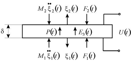
Figure 1. Piezoactuator for the longitudinal piezoelectric effect.
For constructing a structural parametric model of the voltage-controlled piezoactuator, let us solve simultaneously the wave equation, the equation of the inverse longitudinal piezoeffect, and the equation of forces acting on the faces of the piezoactuator. Calculations of the piezoactuators are performed using a wave equation [2,7,9] describing the wave propagation in a long line with damping but without distortions, which can be written as
![]() , (10)
, (10)
where ![]() is the displacement of the section, x is the coordinate, t is time,
is the displacement of the section, x is the coordinate, t is time, ![]() is the sound speed for
is the sound speed for ![]() ,
, ![]() is the damping coefficient. Using the Laplace transform, we can reduce the original problem for the partial differential hyperbolic equation of type (10) to a simpler problem for the linear ordinary differential equation [8, 9]. Applying the Laplace transform to the wave equation (10) and setting the zero initial conditions, we obtain the linear ordinary second-order differential equation with the parameter p
is the damping coefficient. Using the Laplace transform, we can reduce the original problem for the partial differential hyperbolic equation of type (10) to a simpler problem for the linear ordinary differential equation [8, 9]. Applying the Laplace transform to the wave equation (10) and setting the zero initial conditions, we obtain the linear ordinary second-order differential equation with the parameter p
![]() , (11)
, (11)
with its solution being the function
![]() , (12)
, (12)
where ![]() is the Laplace transform of the displacement of the section of the piezoelectric actuator,
is the Laplace transform of the displacement of the section of the piezoelectric actuator, ![]() is the propagation coefficient. Determining coefficients C and B from the boundary conditions as
is the propagation coefficient. Determining coefficients C and B from the boundary conditions as
![]() for
for ![]() , (13)
, (13)
![]() for
for ![]() .
.
Then, the constant coefficients
![]() ,
, ![]() . (14)
. (14)
The solution (11) can be written as
![]() . (15)
. (15)
The equations for the forces on the faces of the piezoactuator
![]() for
for ![]() , (16)
, (16)
![]() for
for ![]() ,
,
where ![]() and
and ![]() are determined from the equation of the inverse piezoelectric effect.
are determined from the equation of the inverse piezoelectric effect.
For ![]() and
and ![]() , we obtain the following set of equations for determining stresses in the piezoactuator [24-26]:
, we obtain the following set of equations for determining stresses in the piezoactuator [24-26]:
![]() , (17)
, (17)
![]() .
.
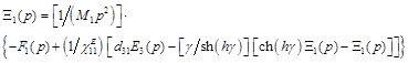
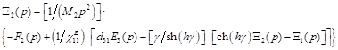
The set of equations (17) yield the set of equations for the structural-parametric model of the piezoactuator Figure 2:
 , (18)
 ,
,
where ![]() .
.
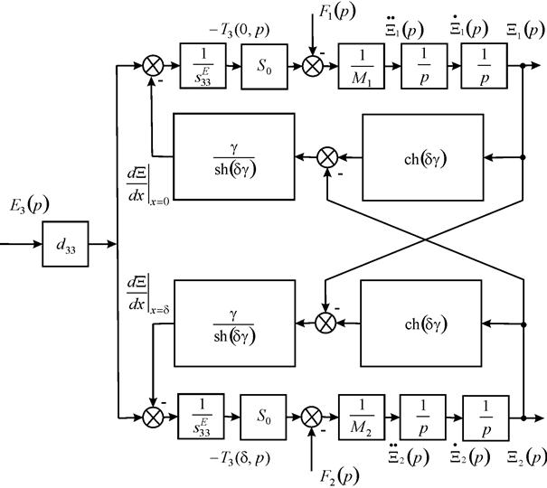
Figure 2. Parametric structural schematic diagram of a voltage-controlled piezoactuator for longitudinal piezoelectric effect.
In the equation (5) of the inverse transverse piezoeffect [7, 9] are the following parameters: ![]() is the relative displacement of the cross section along axis 1 Figure 3,
is the relative displacement of the cross section along axis 1 Figure 3, ![]() is the piezomodule for the transverse piezoeffect,
is the piezomodule for the transverse piezoeffect, ![]() is the elastic compliance along axis 1,
is the elastic compliance along axis 1, ![]() is the stress along axis 1.
is the stress along axis 1.
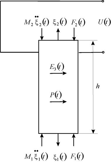
Figure 3. Piezoactuator for the transverse piezoelectric effect.
The solution of the linear ordinary differential equation (11) can be written as (12), where the constants C and B in the form
![]() for
for ![]() , (19)
, (19)
![]() for
for ![]() ,
,
![]()
![]() (20)
(20)
Then, the solution (11) can be written as
![]() (21)
(21)
The equations of forces acting on the faces of the piezoactuator
![]() for x = 0, (22)
for x = 0, (22)
![]() for x = h,
for x = h,
where
![]() (23)
(23)
![]()
The set of equations describing the structural-parametric model and parametric structural schematic diagram Figure 4
 , (24)
 ,
,
where ![]() .
.
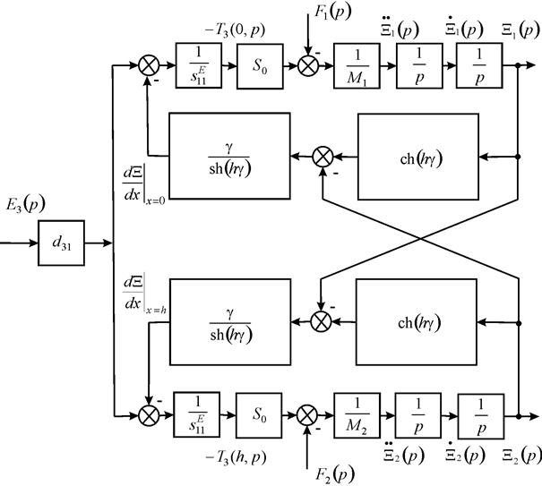
Figure 4. Parametric structural schematic diagram of a voltage-controlled piezoactuator for transverse piezoelectric effect.
Let us consid er the piezoactuator for the shift piezoelectric effect (6) on Figure 5.
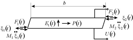
Figure 5. Piezoactuator for the shift piezoelectric effect.
We obtain the following set of equations describing the structural-parametric model and schematic diagram Figure 6
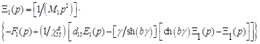 , (25)
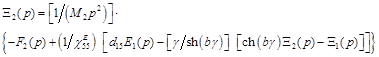 ,
,
where ![]() .
.

Figure 6. Parametric structural schematic diagram of a voltage-controlled piezoactuator for shift piezoelectric effect.
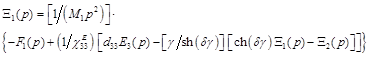
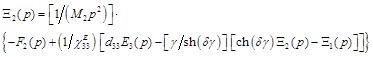
From (3), (18), (24), (25) we obtain the system of equations describing the generalized structural-parametric model of the electromagnetoelastic actuator
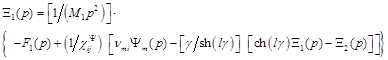 , (26)
 ,
,
![]() ,
,  ,
,  ,
,
 ,
,  ,
,  ,
, ![]() ,
,
where parameters ![]() of the control for the electromagnetoelastic actuator: E for voltage control, D for current control, H for magnetic field strength control. On Figure 7 shows the generalized parametric structural schematic diagram of the electromagnetoelastic actuator corresponding to the set of equations (26) of the actuator for precision engineering.
of the control for the electromagnetoelastic actuator: E for voltage control, D for current control, H for magnetic field strength control. On Figure 7 shows the generalized parametric structural schematic diagram of the electromagnetoelastic actuator corresponding to the set of equations (26) of the actuator for precision engineering.
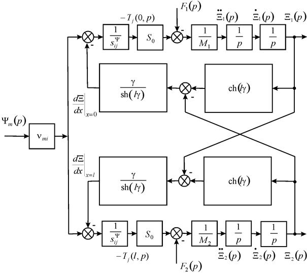
Figure 7. Generalized parametric structural schematic diagram of the electromagnetoelastic actuator.
3. Transfer Functions of Electromagnetoelastic Actuator
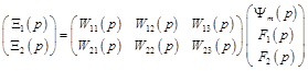
Let us consider the generalized structural-parametric model (26) of the actuator after algebraic transformations provides the transfer functions of the electromagnetoelastic actuator in matrix form [24-26], where the transfer functions are the ratio of the Laplace transform of the displacement of the face actuator and the Laplace transform of the corresponding parameter or force at zero initial conditions.
,(27)
![]() ,
,
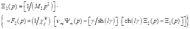
where the generalized transfer functions of the electromagnetoelastic actuator are the following form:
![]() , (28)
, (28)
![]() , (29)
, (29)
![]() , (30)
, (30)
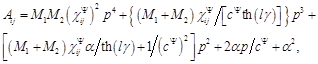
 , (31)
![]() . (32)
. (32)
Therefore, we obtain from equations (27) the generalized matrix equaion for the electromagnetoelastic actuator
 . (33)
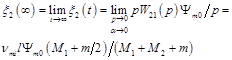
Let us find the displacement of the faces the electromagnetoelastic actuator in a stationary regime for ![]() ,
, ![]() and inertial load. The static displacement of the faces the electromagnetoelastic actuator
and inertial load. The static displacement of the faces the electromagnetoelastic actuator ![]() and
and ![]() can be written in the form
can be written in the form
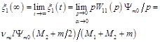 , (34)
 , (35)
![]() , (36)
, (36)
where m is the mass of the electromagnetoelastic actuator, ![]() are the load masses.
are the load masses.
Let us consider a numerical example of the calculation of static characteristics of the piezoactuator from piezoceramics PZT under the longitudinal piezoelectric effect at ![]() and
and ![]() . For
. For ![]() m/V,
m/V, ![]() V,
V, ![]() kg and
kg and ![]() kg we obtain the static displacement of the faces of the piezoactuator
kg we obtain the static displacement of the faces of the piezoactuator ![]() nm,
nm, ![]() nm,
nm, ![]() nm.
nm.
The static displacement the faces of the piezoactuator for the transverse piezoelectric effect and inertial load at ![]() ,
, ![]() and
and ![]() can be written in the following form:
can be written in the following form:
![]() , (37)
, (37)
![]() , (38)
, (38)
![]() . (39)
. (39)
Consider a numerical example for the calculation of static characteristics of the piezoactuator from piezoceramics PZT under the transverse piezoelectric effect at ![]() and
and ![]() . For
. For ![]() m/V,
m/V, ![]() m,
m, ![]() m,
m, ![]() V,
V, ![]() kg and
kg and ![]() kg we obtain the static displacement of the faces of the piezoactuator
kg we obtain the static displacement of the faces of the piezoactuator ![]() μm,
μm, ![]() μm,
μm, ![]() μm.
μm.
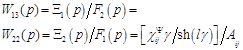
For the description of the piezoactuator for the longitudinal piezoelectric effect for one rigidly fixed face of the transducer at ![]() we obtain from equation (29) and (32) the transfer functions
we obtain from equation (29) and (32) the transfer functions ![]() and
and ![]() of the piezoactuator for the longitudinal piezoelectric effect in the following form:
of the piezoactuator for the longitudinal piezoelectric effect in the following form:
,(40)
![]() . (41)
. (41)
Accordingly, the static displacement ![]() of the piezoactuator under the longitudinal piezoeffect in the form
of the piezoactuator under the longitudinal piezoeffect in the form
![]() , (42)
, (42)
![]() . (43)
. (43)
Consider a numerical example for the calculation of static characteristics of the piezoactuator under the longitudinal piezoeffects. For ![]() m/V,
m/V, ![]() V we obtain
V we obtain ![]() nm. For
nm. For ![]() m,
m, ![]() m2/N,
m2/N, ![]() N,
N, ![]() m2 we obtain
m2 we obtain ![]() nm. The experimental and calculated values for the piezoactuator are in agreement to an accuracy of 5%.
nm. The experimental and calculated values for the piezoactuator are in agreement to an accuracy of 5%.
Let us consider the operation at low frequencies for the piezoactuator with one face rigidly fixed so that ![]() and
and ![]() . Using the approximation of the hyperbolic cotangent by two terms of the power series in transfer functions (40) and (41), at
. Using the approximation of the hyperbolic cotangent by two terms of the power series in transfer functions (40) and (41), at ![]() we obtain the expressions in the frequency range of
we obtain the expressions in the frequency range of ![]()
![]() , (44)
, (44)
![]() , (45)
, (45)
![]() ,
, ![]() ,
,
![]() .
.
where ![]() is the time constant and
is the time constant and ![]() is the damping coefficient,
is the damping coefficient, ![]() - is the is rigidity of the piezoactuator under the longitudinal piezoeffect.
- is the is rigidity of the piezoactuator under the longitudinal piezoeffect.
In the static mode of operation the piezoactuator for elastic load we obtain the equation the following form
![]() , (46)
, (46)
where ![]() is the displacement of the piezoactuator in the case of the elastic load,
is the displacement of the piezoactuator in the case of the elastic load, ![]() is the maximum displacement of the piezoactuator,
is the maximum displacement of the piezoactuator, ![]() is the load rigidity.
is the load rigidity.
From (44), (46) we obtain the transfer functions of the piezoactuator with a fixed end and elastic inertial load
![]() , (47)
, (47)
where the time constant ![]() and the damping coefficient
and the damping coefficient ![]() are determined by the formulas
are determined by the formulas
![]() ,
, ![]() .
.
Let us consider the operation at low frequencies for the piezoactuator with one face rigidly fixed and elastic inertial load so that ![]() and
and ![]() for
for ![]() kg,
kg,![]() N/m,
N/m, ![]() N/m we obtain
N/m we obtain ![]() c.
c.
4. Results and Discussions
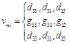
The structural-parametric model and the generalized parametric structural schematic diagram of electromagnetoelastic actuator for precision engineering are obtained taking into account equation of generalized electromagnetoelasticity (piezoelectric, piezomagnetic, electrostriction, and magnetostriction effects) and decision wave equation. The results of constructing the generalized structural-parametric model and the generalized parametric structural schematic diagram of electromagnetoelastic actuator for the longitudinal, transverse and shift deformations are shown in Figure 7. The parametric structural schematic diagrams piezoelectric actuator for longitudinal, transverse, shift piezoelectric effects Figure 2, Figure 4, Figure 6 converts to the generalized parametric structural schematic diagram of the electromagnetoelastic actuator for precision engineering Figure 7 with the replacement of the following parameters:
![]() ,
, ![]() ,
, ![]() ,
, ![]() .
.
The generalized structural-parametric model and the generalized parametric structural schematic diagram of the electromagnetoelastic actuator after algebraic transformations provides the transfer functions of the electromagnetoelastic actuator actuator for precision engineering. The piezoelectric actuator with the transverse piezoelectric effect compared to the piezoelectric actuator for the longitudinal piezoelectric effect provides a greater range of static displacement and a less working force. The magnetostriction actuators provides a greater range of static working forces.
It is possible to construct the generalized structural-parametric model, the generalized parametric structural schematic diagram and the transfer functions in matrix form of the electromagnetoelastic actuator for precision engineering using the solutions of the wave equation of the electromagnetoelastic actuator and taking into account the features of the deformations actuator along the coordinate axes.
5. Conclusions
The systems of equations are determined for the structural-parametric models of the piezoactuators. The transfer functions and the parametric structural schematic diagrams of the piezoactuators for the transverse, longitudinal, shift piezoelectric effects are obtained from structural-parametric models of the piezoactuators. Using the obtained solutions of the wave equation and taking into account the features of the deformations along the coordinate axes, it is possible to construct the generalized structural-parametric model and parametric structural schematic diagram of the electromagnetoelastic actuator for precision engineering and to describe its dynamic and static properties.
The transfer functions in matrix form of the electromagnetoelastic are describe deformations actuator during its operation as a part of the control systems for precision engineering.
References


