| 1. | ||
| 2. | ||
| 3. | ||
| 4. | ||
| 5. | ||
| 6. | ||
| 7. | ||
The Calculation and Optimal Control by the Technological Processes of a Puller Shaft Turning Processing
Azimov B. M., Sulyukova L. F.
Centre for Development Hardware and Software Products, IT University, Tashkent, Uzbekistan
Email address
 (Azimov B. M.)
  (Sulyukova L. F.)
 Citation
Azimov B. M., Sulyukova L. F. The Calculation and Optimal Control by the Technological Processes of a Puller Shaft Turning Processing. American Journal of Science and Technology. Vol. 4, No. 1, 2017, pp. 5-12.
Abstract
The questions of application of modern methods and algorithms for the optimal control on technological processes for a cotton-harvester machines’ harvester device puller shaft turning processing are considered in the article. Components of the cutting force and meanings of axis stretching force by turning are determined. The necessary conditions of the technological system optimal control are investigated through the use of the Pontryagin maximum principle. The optimal values of geometrical, constructive and functional parameters of the processed workpiece are obtained.
Keywords
Technological System, Functioning, In-Process Workpiece, Mathematical Modeling, Optimal Control
1. Introduction
The puller of cotton-harvesting machine device consists of the shaft with length lv=0.95m, diameter d=0.026m and taking off brushes mounted into its section which have the function to take off reeled by spindle raw cotton for throwing into the entrance camera to transport into the machine bunker. Mainly, the puller work efficiency demands on its details, especially the shaft producing accuracy. One of the main ways of puller shaft mechanical processing is the turning [1−4].
The determinative research phase is the control object formalization to determine the capacity to apply computing methods in the research process. When the task is formalized completely, i.e. the completed mathematic model is available; it may be solved by one of numerical methods using the computing device.
2. Construction of the Kinematic Scheme and Dynamic Models
The kinematic scheme and the dynamic model of the technological system (TS) were built to develop mechanical processing ways (figure 1, 2). Using the second kind Lagrange equation the math model of TS puller shaft turning processing was formed [5],
![]() (1)
(1)
where j1, j2 – TS rotating masses inertion moments, N×m×s2;![]() − TS rotating masses corner accelerations in the processing, s-2;
− TS rotating masses corner accelerations in the processing, s-2;![]() − TS rotating masses corner speeds in the processing, s-1;
− TS rotating masses corner speeds in the processing, s-1;![]() − TS rotating masses corner shifts in the processing, rad; b – the coefficient of sticky resistance of in-processing shaft, N×m×s/rad; с − the coefficient of rigidity of in-processing shaft, N×m/rad; Мd, Мr –TS driving and resistance moment, N×m.
− TS rotating masses corner shifts in the processing, rad; b – the coefficient of sticky resistance of in-processing shaft, N×m×s/rad; с − the coefficient of rigidity of in-processing shaft, N×m/rad; Мd, Мr –TS driving and resistance moment, N×m.
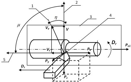
Figure 1. The kinematic elements and cutting characteristics: 1–speed direction of the cutting resulting moving; 2−speed direction of the cutting main moving; 3–workplate; 4–the examining point of cutting edge; 5−speed direction of the feed moving.
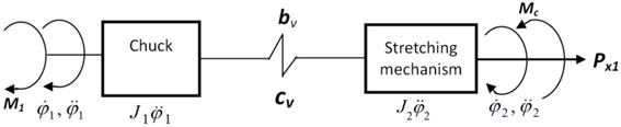
Figure 2. TS dynamic model.
3. Calculation of Cutting Force Components
The cutting force components meanings Px, Py, Pz are determined by the technological conditions that means the cutting geometrical regimes [6, 7].
The cutting force components by the turning are calculated by the analytical formula
Pz(x,y)=10∙Cp∙![]() ∙Sy∙Vn∙Kp= 10 300
∙Sy∙Vn∙Kp= 10 300
0.11·0.0820.75·0.102835-0.15·0.5394=34.822N,
where Cp=300–the coefficient accounting processing conditions; x=1.0, y=0.75, n=-0.15 – degree indexes; tр=0.1mm – cutting deep; S=0.082 mm/rot − feed; V=102.835 mm/min=0.102835 m/min –cutting speed; Кр–total correction coefficient accounting conditions changing with the reference to table ones:
![]()
where![]() − correction coefficient accounting the in-processing material properties;
− correction coefficient accounting the in-processing material properties; ![]() − coefficients accounting corresponding geometrical chisel parameters.
− coefficients accounting corresponding geometrical chisel parameters.
By elastic small rigidity details lines model building and by their processing in the elastic deformed state bending moments on X axis are taken in to account as more essential qualities, so as elastic deformations on this axis exert dominated influence to form an error in the longitudinal direction.
Relative longitudinal deformations of in-processing shaft by the stretching [8]
![]() .
.
Absolute shaft extension by the stretching
![]() ,
,
then the permissible meaning of stretching force is
![]() ,
,
where ![]() −the permissible stress by stretching; F – the area of shaft cross-section.
−the permissible stress by stretching; F – the area of shaft cross-section.
Taking into account axis stretching force and the absolute extension of in-processing shaft by the stretching relative longitudinal deformation scan be determined by the Hook slaw [8]
![]() .
.
Then the calculation meaning of axis stretching force will be equal in our case
![]()
Preliminary necessary shaft rigidity in the corresponding moment of resistance is determined [8]
s

![]()
Rigidity and sticky resistance coefficient are determined by rolling and stretching
![]()
![]()
![]()
where ![]() и
и![]() − shaft rolling corners by rolling and stretching rigidity; cк, cр и cv– coefficient of rigidity by rolling, transfor-mated rigidity by rolling and total rigidity of in-processing shaft; bv – coefficient of shaft sticky resistance; l–in-processing shaft length; G, E–shaft material displacement and elastic modules; Jp– polar and axis inertion moments; F–shaft cross-section area; rв – in-processing shaft diameter;
− shaft rolling corners by rolling and stretching rigidity; cк, cр и cv– coefficient of rigidity by rolling, transfor-mated rigidity by rolling and total rigidity of in-processing shaft; bv – coefficient of shaft sticky resistance; l–in-processing shaft length; G, E–shaft material displacement and elastic modules; Jp– polar and axis inertion moments; F–shaft cross-section area; rв – in-processing shaft diameter; ![]() − process frequency.
− process frequency.
4. Solution of Optimal Control Problem
According to above-mentioned, the task of TS optimal control can be choose [9, 10].
In the beginning TS is instate
![]() (2)
(2)
It is required to choose such control u(t), which transfer in-processing shaft moving into the beforehand set final state
![]() (3)
(3)
By the way it is required, the transition process time was the least. So the control aim reduces to functional minimization.
![]() . (4)
. (4)
By conditions (2), (3)
![]() (5)
(5)
![]() (6)
(6)
where f(…)– persistent differential function with its derivations; u(t)–piece wise persistent function on the segment [t0, T].
To investigate the TS optimal control necessary conditions we use Pontryagin maximum principle [9, 10].
To formulate the maximum principle we enter the Hamilton-Pontryagin function for TS
![]() (7)
(7)
and adjoin system
 (8)
(8)
with control limit ![]()
The necessary condition must be to the task decision
![]() . (9)
. (9)
Moving to the optimal control determining on the base of (7), we form the function
 , (10)
and get the math model characterizing the control ![]() by in-processing shaft driving and the control
by in-processing shaft driving and the control ![]() ,
,![]() (u0–its fluctuation amplitude relatively of the middle index), characterizing the force in the instrument putting point.
(u0–its fluctuation amplitude relatively of the middle index), characterizing the force in the instrument putting point.
So, if ![]() then
then ![]() , in this case the task (2)−(6) is named as the rapid operation task.
, in this case the task (2)−(6) is named as the rapid operation task.
The object is the steady-state system and the task (4) means, that![]() don`t depend on the time clearly that means
don`t depend on the time clearly that means
![]() . (11)
. (11)
If the steady-state task (4), (11) has the optimal control u(t) and the optimal trajectory ![]() , so there is non-zero vector of conjugate variables
, so there is non-zero vector of conjugate variables ![]() , meeting the conditions (9), that means the maximum condition was performed (7)
, meeting the conditions (9), that means the maximum condition was performed (7)
![]() . (12)
. (12)
So as the adjoin system (8) is homogeneous relatively of![]() , the equation constant can be choosen arbitrarily (12) so that
, the equation constant can be choosen arbitrarily (12) so that
![]() . (13)
. (13)
From the conditions ![]() is
is ![]() by
by ![]() Then the boundary value problem of the maximum principle will be written as
Then the boundary value problem of the maximum principle will be written as
![]() . (14)
. (14)
In these cases the boundary value problem of the maximum principle will consist of system (14), boundary conditions (2) and (3), are from (9), and condition (13).
Form Hamilton-Pontryagin function
![]() (15)
(15)
It is clear, that condition (9) will give off the function![]() In this case the boundary value problem (10), (14) consists of [10]
In this case the boundary value problem (10), (14) consists of [10]
![]() . (16)
. (16)
Then
![]() , k=2,4,…,2n, (17)
, k=2,4,…,2n, (17)
that means the control uk(t) can have only one switching point.
5. Discussion of Experimental Results
The adjoin system with variations of constructive parameters was investigated to determine the auxiliary function (8) by the numerical method bi, сi, ji.
Systems (1), (8), (14) were decided by the Runge-Kutta numerical methods application. The control uk(t), giving the function maximum (9), was determined in the field (17). System decisions results processing (8) were, that inertion moments and elastic and dissipative forces changing change the variables ![]() ,
,![]() ,
,![]() ,
,![]() function, that means it changes in-processing shaft driving. So it is necessary to determine the adjoin system variables, providing TS normal functioning to increase the accuracy in-processing shafts form and dimensions [10].
function, that means it changes in-processing shaft driving. So it is necessary to determine the adjoin system variables, providing TS normal functioning to increase the accuracy in-processing shafts form and dimensions [10].
On the base of received parameters bi, сi, ji for decision of adjoin system and boundary volume problem of the maximum principle graphic depending of in-processing shaft speeds and accelerations in transition process were got (figure 3).
The graph shown in figure 3 gives the results of the solution of the control algorithm at ![]() .
.
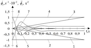
Figure 3. Graphics of auxiliary functions 1,3−![]() ,
, ![]() ; 2,4−
; 2,4−![]() ,
, ![]() changing in transition process getting by (14) the maximum principle boundary value problem solving: 5,7 – corner speeds
changing in transition process getting by (14) the maximum principle boundary value problem solving: 5,7 – corner speeds ![]() and 6,8 – corner accelerations
and 6,8 – corner accelerations ![]() of the shaft: 1,2,5,6 − by u(t)=+1; 3,4,7,8− by u(t)=-1.
of the shaft: 1,2,5,6 − by u(t)=+1; 3,4,7,8− by u(t)=-1.
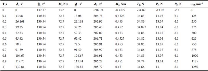
The results of system numerical decisions (1), represented in tables 1, 2 and on figure 4, take possibility to determine the geometrical, constructive and functional parameters of in-processing shaft.
Table 1. Meanings and indexes of in-processing puller shaft geometrical, constructive and functional parameters.
| № | Parameters | Meaning | Index | |
| 1 | 2 | 3 | 4 | |
| 1. | Geometric dimensions of the in-processing shaft | |||
| 1.1. | Length of the in-processing shaft | 950 | mm | |
| 1.2. | Diameter of the in-processing shaft | 26 | mm | |
| 2. | Processing conditions: | |||
| 2.1. | Cutting speed − | 102.835 | mm/min | |
| 2.2. | Feed − | 0.082 | mm/rot | |
| 2.3. | Processing period − Т | 9.27 | min | |
| 2.4. | Cutting deep − tр | 0.1 | mm | |
| 2.5. | The shaft number of rotations – n | rot/min | ||
| 3. | Constructive characteristics of the in-processing shaft | |||
| 3.1. | Material − steel 35 | |||
| 3.2. | Permissible stress by stretching − sр | 900 | kgs/mm2 | |
| 3.3. | Solidity limit −s | 0.35×HB | kgs/mm2 | |
| 3.4. | Total coefficient of the in-processing shaft rigidity – сv | 55685.144 | N×m/rad | |
| 3.5. | Coefficient of the in-processing shaft rolling rigidity – ск | 2799.63 | N×m/ rad | |
| 3.6 | Coefficient of the in-processing shaft rigidity by stretching – ср | 52885.514 | N×m/ rad | |
| 3.7. | Total coefficient of the in-processing shaft sticky resistance − bv | 43.376 | N×m-s/rad | |
| 3.8. | Inertion moment of machine cartridge - j1 | 0.56755 | N×m×s2 | |
| 3.9. | Inertion moment of stretching mechanism-j2 | 0.002938 | N×m.s2 | |
| 3.10. | Eccentricity−е | 1.0 | mm | |
| 4. | Parameters of TS functioning | |||
| 4.1. | Driving moment − М1 | 73.597828 | N×m | |
| 4.2. | Force in direction of cutting speed− Pz | 34.822 | N | |
| 4.3. | Resistance moment М2= rsh ·Pz | 0.4527 | N×m | |
| 4.4. | Calculation index of axis stretching force − Px1 | 34.822 | N | |
| 4.5. | Absolute shaft extension by stretching − | 0.00000011 | m | |
| 4.6. | Coefficient of storage fixing | 3.28474 | ||
| 4.7. | The shaft turn corner by bend | 0.5 | rad | |
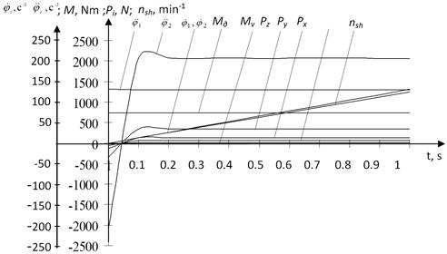
Figure 4. The manner of parameters changing of technological process functioning by the puller of cotton-harvester machine device turning.
Figure 4 allows graphically display the results of the solution of a mathematical model of the technological system of the puller shaft turning processing (1).
Table 2. Parameters meanings of functioning of the shaft processing technological process.
There are analogue empirical formulas to determine the forces Py and Px. But to simplify and accelerate the forces index calculation it is recommended to decide Py and Px accordingly the following correlations [4]:
Pz=34.822H,Py=(0.25−0.5)·Pz,Px=(0.1−0.25)·Pz,![]()
![]()
![]() ,
,
where rsh – radius of the in-processing shaft.
6. Establishing of Theoretical Conformities of a Detail Conduct by Longitudinal-Diametrical Bend
The equation of unrigged shaft elastic line was decided on the base of the calculation scheme to evaluate possibilities of methods and establish theoretical conformities of a detail conduct by longitudinal−diametrical bend (figure 5).
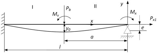
Figure 5. Calculation scheme of stresses and elastic line of the shaft by stretching: е=0.001– eccentricity of stretching force putting; Мv–cutting forces moment; Mx=Px1∙e=34.822·0.001=0.034822 Nm –stretching effort moment.
Description of unrigged shaft elastic line by longitudinal and diametrical bend can be represented in form of the fourth order differential equations with the constant coefficients [11].
![]() . (18)
. (18)
This equation decision gives the total elastic line equation for stretching and performing arbitrary diametrical leading beam
![]()
where ![]() ,
, ![]() − accordingly deflection, turn corner, the second and the third derivates in the coordinates beginning [8];
− accordingly deflection, turn corner, the second and the third derivates in the coordinates beginning [8]; ![]() − coefficient determining the storage fixing method [12]; f(x)–function of diametrical loading influence [11].
− coefficient determining the storage fixing method [12]; f(x)–function of diametrical loading influence [11].
Elastic line equations on segments I and II (calculation scheme figure 5) are
![]() .(19)
.(19)
The initial parameters are determined by the following:

![]() ,
,
where ![]() ; l–detail length; a–coordinate of diametrical loading putting.
; l–detail length; a–coordinate of diametrical loading putting.
Taking into account that the stretching moment was putat the coordinates beginning it is necessary to determine the initial parameter ![]() . We find it by differentiation of (19).
. We find it by differentiation of (19).
![]() . (20)
. (20)
After the multiplication of (20) to bending and stretching rigidity we will get the equation of bending moment on segment I, taking into account
![]() ;
;![]() .
.
Then
![]() . (21)
. (21)
If by х=0, МI(0)=M, so from (21) is [8]
![]() ,
,
where![]() .
.
The function of diametrical loading influence
![]() .
.
Finally, deflections equations on segments will be

where ![]() ;
; ![]() .
.
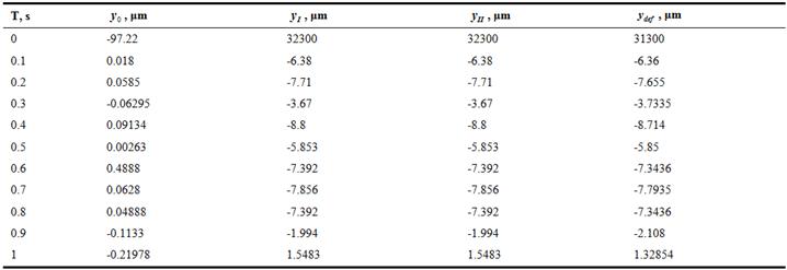
On the base of the system numerical decisions (1) and calculation scheme deflections and puller shaft processing accuracy were calculated, the results were represented in table 3 and on figures 5, 6.
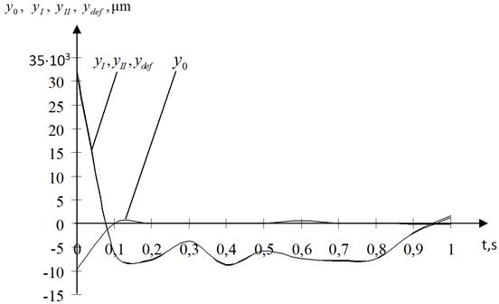
Figure 6. The manner for accuracy changing of technological process functioning of the puller turning of cotton-harvester machine device.
Table 3. The results of calculation of deflections and puller shaft processing accuracy.
7. Conclusion
The influence of inertion moments and elastic and dissipative forces to changing of in-processing shaft moving was investigated. Changing of TS front and back beams inertion moment influences essentially to in-processing shaft corner speed sand accelerations. The variation of in-processing shaft coefficients of rigidity, sticky resistance and stretching forces was performed to reduce the range of corner speeds and accelerations changing. Rigidity increase at the expense of stretching lead to reducing of in-processing shaft deformation and reducing of transition process. The amplitude of corner speeds fluctuations is reduced considerably by the increase of in-processing shaft sticky resistance coefficient. It confirms that the amplitude and frequency of in-processing shaft corner speeds and accelerations fluctuations depend on the inertion moment and elastic and dissipative forces. Thus, corresponding meanings of driving moment, stretching force and cutting forces moments were determined for set meaning of in-processing shaft inertion moments of rotating masses and rigidity and sticky resistance coefficients.
References


