| 1. | ||
| 2. | ||
| 3. | ||
| 3.1. | ||
| 3.2. | ||
| 3.3. | ||
| 4. | ||
Mechanical Problems Facing a Ni-Cr Reinforced Bi-2223/Ag Conductor
M. Nawa, H. Nakagome
Graduate School of Engineering, Chiba University,Chiba, Japan
Email address
 (M. Nawa)
 Citation
M. Nawa, H. Nakagome. Mechanical Problems Facing a Ni-Cr Reinforced Bi-2223/Ag Conductor. American Journal of Science and Technology. Vol. 4, No. 1, 2017, pp. 1-4.
Abstract
The tensile stress tolerance of a Bi-2223 conductor has been improved using a mechanically strong Ni-Cr reinforcement and pre-tension technique. The resulting high-strength Bi-2223 has the potential to realize a super-high field compact NMR magnet and is anticipated as a next-generation high-temperature superconductor. However, it was found that fracture issues such as buckling and peeling of the Ni-Cr reinforcement occurred upon exposure of the conductor to excessively high temperature. Moreover, the critical current value and tensile stress tolerance were greatly degraded at high temperature. That is, if an excessive temperature rise such as thermal runaway occurs in the practical scale coil, there is a possibility of a dangerous phenomenon such as arc discharge occurring from the buckled part and accompanying equipment damage. The aims of this study are to investigate the mechanism of fracture of High-strength Bi-2223 and develop preventative technology.
Keywords
Neculear Magnetic Resonance (NMR), High-Temperature Superconductor, Thermal Runaway, Buckling, High-Strength Bi-2223
1. Introduction
Three types of high-temperature superconductors suitable to achieve an NMR magnet that operates beyond 1 GHz are available; namely, REBCO conductors [1, 2, 3, 4, 5], Bi-2223 multifilament tape conductors [6, 7], and Bi-2212 multifilament round conductors [8]. In particular, high-strength Bi-2223 developed based on conventional Bi-2223 is expected to achieve NMR magnets that operate beyond 1 GHz because its tensile strength tolerance has been improved from ~250 MPa to 400–500 MPa through Ni-Cr reinforcement in combination with pre-tension technique of Bi-2223 filaments and an Ag matrix [9]. This high-strength Bi-2223 conductor is promising for development of super-high field NMR magnets. However, when we soldered the high-strength Bi-2223 conductor to the innermost layer of a coil, all the layers of the coil fractured. In addition, in another experiment, when thermal runaway occurred in a double pancake coil with a high-strength Bi-2223 conductor, the Bi-2223 filament/Ag structure completely buckled and the Ni-Cr reinforcement peeled off [10]. If such fracture transpires in a practical-scale coil, it is assumed that arc discharge will occur from the buckled part because of high-current-density operation. The purpose of this study is to clarify the mechanism of fracture with the aim of developing a method to prevent fracture in high-strength Bi-2223.
2. Experimental
Fracture was generated in high-strength Bi-2223 by excessive temperature rises such as soldering at the innermost layer and thermal runaway. The cause of fracture in part of the high-strength Bi-2223 conductor at high temperature was investigated. The experiment involved heating part of the high-strength Bi-2223 conductor. The experimental setup used to heat part of the high-strength Bi-2223 conductor is shown in Figure 1. An aluminum block on a hot plate was used to heat the conductor to a temperature of 580 K. The conductor was fixed to a cement block that acted as a body with low thermal conduction. A thermocouple and strain gauge were positioned on the conductor surface to measure the temperature rise of the conductor.
The second experiment was a method to prevent buckling caused by temperature rise. This experiment was designed based on the experiment used to clarify the mechanism of fracture. The experimental setup is displayed in Figure 2. The cement block and aluminum block on the hot plate were the same as those in the experiment used to clarify the fracture mechanism. The conductor was heated up to 580 K. The load used was encased water. The critical current value at each pressure was measured after heating.
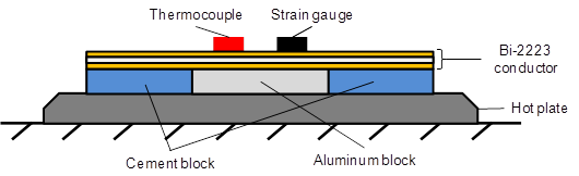
Figure 1. Experimental setup to cause fracture of Bi-2223. The aluminum block is a high-temperature conductor and the cement block is a low-temperature conductor used as a foundation to heat part of the conductor. The heat from the hot plate propagated to the conductor. A thermocouple and strain gauge were positioned on the conductor surface.
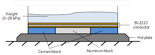
Figure 2. Experimental setup to prevent fracture of Bi-2223. The basic specifications are the same as in Figure 1. Water in a container was used to apply radial compressive stress to the surface of the conductor. The radial compressive stress was adjusted by increasing the amount of water.
3. Results and Discussion
3.1. Heating Part of the High-Strength Bi-2223 Conductor
The results of the experiment that involved heating part of the high-strength Bi-2223 conductor are presented in Figure 3. The measured strain as temperature rose can be divided into three stages, as discussed below. Figure 4 shows photographs of the conductor before and after heating part of it.
Tensile strain of 0.16% was generated as temperature rose until the temperature of the conductor surface reached 400 K. This tensile strain was caused by melting of the solder between the Ni-Cr reinforcement on the heating side and Bi-2223 filaments/Ag induced by the temperature rise. Solder melting released the internal strain generated in the Ni-Cr reinforcement by the pre-tension technique. Melting caused the Ni-Cr reinforcement to deform to a mountain shape.
When the temperature of the conductor surface reached 495 K, compressive strain of 0.08% was generated through melting of the solder layer on the surface side. This compressive strain was generated by the same mechanism as that in (1).
When compressive strain of 0.13% was generated, buckling occurred in the conductor. The temperature of the conductor surface at this time was 445 K. Photographs of the conductor before and after the experiment are displayed in Figure 4.
These results reveal that the cause of buckling is release of the internal strain of the Ni-Cr reinforcement arising from the pre-tension technique. The release of the internal strain is caused by melting of the solder in the conductor as the temperature rises.
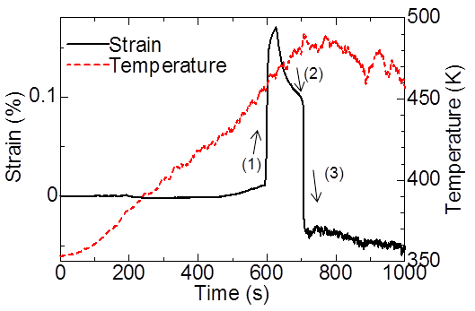
Figure 3. Strain in Bi-2223 as part of it was heated. (1) Tensile strain of 0.16% was generated by melting of the solder layer on the heating side. (2) Compressive strain of 0.08% was generated by melting of the solder layer on the surface side. (3) Compressive strain was generated by the solder melting completely.
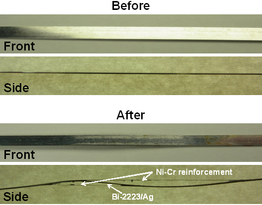
Figure 4. Comparison of the conductor before and after the heating experiment.
3.2. A Method to Prevent Buckling of Bi-2223 at Elevated Temperature
The results obtained using a method to prevent buckling of Bi-2223 caused by the temperature rising are presented in Figure 5. The critical current value of the normal state is 193 A, which is used as the standard to measure the critical current value after the experiment. The critical current was 152 A at 4.4 kPa, which is the largest decrease at any pressure from the radial direction. At other pressures, a decrease of the critical current value was observed. However, at 17.4 kPa, the measured critical current value was 193 A, which is the same as the normal state of the conductor. This is important because it reveals that a low pressure of 17.4 kPa from the radial direction can prevent buckling of Bi-2223.
The Bi-2223 filaments and Ag matrix in the buckled part were bent along with separation of the Ni-Cr reinforcements. However, such buckling was not generated at 17.4 kPa because the critical current value did not decrease. For this reason, it was assumed that the bending of the Bi-2223 filaments and Ag matrix was the main cause of the decrease of the critical current value as the conductor was heated.
Therefore, the all bend radius of the Bi-2223 filaments/Ag matrix generated by buckling was measured using an optical microscope. The results of a measurement of the all bend radius of the Bi-2223 filaments/Ag matrix are provided in Figure 6. The smallest bend radius was 3.1 mm at 4.4 kPa. In contrast, the biggest bend radius was 8.6 mm at 13.0 kPa. This correlation matches the trend of the critical current value decrease also displayed in Figure 6.
The bending radius of Bi-2223 filaments/Ag caused by buckling dominated the decrease of the critical current value. Therefore, even if high-strength Bi-2223 is heated to high temperature to melt the solder between the Ni-Cr reinforcement and Bi-2223 filaments/Ag, a low transverse compressive stress such as 17 kPa can prevent the buckling of Bi-2223.

Figure 5. Transition of critical current caused by pressure increase. The horizontal axis shows the applied radial compressive stress and the vertical axis represents the critical current value corresponding to the applied radial compressive stress.
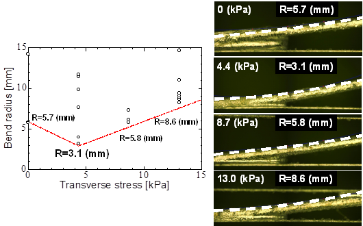
Figure 6. Results from the measurement of the bend radius at each pressure and the smallest bend radius at each pressure. The horizontal axis shows the applied radial compressive stress and the vertical axis shows the diameter of buckling corresponding to the applied radial compressive stress.
3.3. Further Discussion
It was found that the pressure from the radial direction required to prevent buckling of the conductor at elevated temperature is relatively small. Therefore, the following method to prevent buckling of the conductor was devised.
Insulation of the conductor
A half wrap of polyimide tape has been used as a method to insulate the conventional Bi-2223 conductor. However, this insulation method is not effective to prevent buckling because the polyimide tape easily gets loose. However, the polyimide electrodeposition method has the potential to prevent buckling of high-strength Bi-2223. This method involves coating the Bi-2223 conductor with polyimide. Therefore, it is easier to generate pressure from the radial direction to prevent buckling compared with using the half wrap approach. Furthermore, the Young's modulus of the polyimide used in the electrodeposition method is directly reflected as the strength needed to prevent buckling. Thus, it is possible that buckling is prevented by high Young's modulus of polyimide [12].
Epoxy impregnation
It is assumed that buckling can be prevented when epoxy is fixed to the conductor in the radial direction. However, it has been reported that a REBCO coil showed remarkable deterioration following epoxy impregnation [14]. If high-strength Bi-2223 is susceptible to cleavage stress, this phenomenon has the possibility to cause buckling in the high-strength Bi-2223 coil. Accordingly, further examination is necessary to assess the suitability of this method for buckling prevention in Bi-2223.
4. Conclusions
The occurrence of buckling and its prevention in high-strength Bi-2223 were investigated. It was found that the coil was destroyed because of buckling caused by melting of the solder in the conductor as the temperature rose. Such buckling can be prevented by applying pressure from the radial direction. If buckling can be prevented, the critical current value does not decrease. Because the pressure from the radial direction necessary to prevent buckling was relatively small, it became clear that buckling may be prevented by using an existing coil production method such as conductor insulation or epoxy impregnation. However, further verification of the suitability of these approaches to prevent buckling of high-strength Bi-2223 is necessary.
References


