Minimization of Micro Discharge in Space TWT for Long Life Satellite Communication
Vishnu Srivastava
Microwave Tubes Division, CSIR-Central Electronics Engineering Research Institute (CSIR-CEERI), Pilani-333031, Rajasthan, India
Email address
Citation
Vishnu Srivastava. Minimization of Micro Discharge in Space TWT for Long Life Satellite Communication. International Journal of Electrical and Electronic Science. Vol. 3, No. 1, 2016, pp. 1-7.
Abstract
Critical technologies for minimizing micro discharge inside a space TWT are presented for long life and high reliability tube operation for satellite communication. UHV grade materials of low vapor pressure and low gas diffusion rate are used for tube fabrication. High purity alumina insulators are used in gun and collector assemblies with high voltage breakdown margin twice the operating voltage and leakage current less than 0.01µA. Ceramic to metal joints are fabricated to minimize triple-junction effects and to avoid charging of insulators due to any stray electron. High purity low loss alumina insulators (99.5%) are used for RF windows. RF coupler is fabricated to avoid multipactor discharge with a margin of 4 times the operating power output. All assemblies are brazed using Cu-Au alloys, and are checked for leak rate less than 10-12 torr litre/sec. The tube is UHV processed at 550°C for more than 100 hrs for ultimate vacuum inside tube less than 10-10 torr to minimize discharging over the tube life.
Keywords
Amplifier, Ceramic Insulators, Discharge, Microwave Tube, Space TWT, Satellite Transponder, UHV Device, UHV Materials
1. Introduction
Travelling-Wave Tubes (TWTs) [1-2] are used as high power microwave amplifiers in almost all ground and satellite communication systems because of their wide instantaneous bandwidth compared to other microwave tubes. Among various high power microwave tubes, communication TWT particularly for on-board satellite communication is the most critical ultra-high vacuum device. TWTs are an integral part of the satellite transponders used in most commercial and military applications: navigation, radio and television broadcasting, military and commercial data transmissions, internet, earth and planetary observation. For FM and digital communications and for direct TV broadcast systems, TWTs are widely used. Space-borne TWTs are required at frequencies from L-band (1.5GHz) to V-band (60GHz) and now extended up to W-band (94GHz) and power level up to 250 watts. Tube technologies for space TWTs [3-6] have been consistently developed that have led to decisive improvements in space TWT efficiency and thermal performance. Space TWTs have been developed to the point where they possess the RF power output and efficiency, and the reliability, to meet 15-year (uninterrupted) service life requirements of orbital systems. Most critical issue is to minimize discharge in space TWT for long life and high reliable tube operation. In this paper, design of a typical high efficiency space TWT and some of the critical technologies for minimizing micro discharge inside a space TWT are presented.
2. Design of a Space TWT
Fig. 1 shows schematic diagram of a radiation-cooled Ku-band, high efficiency, space TWT. The complete tube with packaging and radiator was designed using in-house developed codes and other commercial 3-D codes like CST, ANSYS, and MAGIC. Major components of a space TWT are: Electron gun for forming of an electron beam of required beam voltage, beam current and beam radius; RF structure for slowing down the RF wave to interact with the electron beam propagating through the structure; PPM focusing (periodic permanent magnets of material Samarium-Cobalt) for focusing of the electron beam through RF structure with minimum scalloping and minimum beam interception; Output coupler for coupling of the RF output power from the RF structure; and Collector (generally four-stage depressed collector) for efficiently collecting of the spent electron beam with minimum loss in energy and minimum back streaming. The tube is mounted with the base plate and isotropic fin-type radiator. All assemblies of a space TWT are very much complex compared to other microwave tubes because of the large number of small-size parts with high precision in fabrication. Electro-polishing on all parts and plasma cleaning on all insulators are done for minimizing discharge by all materials inside the tube. All assemblies (electron gun, SWS, collector) are integrated with optimum precision. Magnetic shunts are used for optimizing electron beam transmission better than 99.9% from gun to collector both under DC and RF operating conditions.
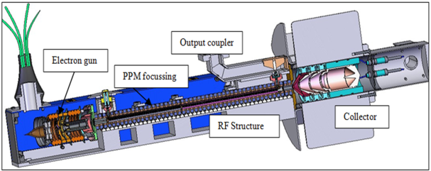
Fig. 1. Schematic diagram of a radiation-cooled Ku-band Space TWT.
For meeting the stringent space requirements, ultra-high vacuum technologies are thoroughly considered for high reliability, long life, low weight and high efficiency of these ultra-high vacuum devices. Because of the continuous long life tube operation, all high voltage gun and collector assemblies of a space TWT with electrical insulators and electrodes are carefully designed for sufficient high voltage margin (more than twice the operating voltages). Also, all assemblies are designed to avoid charging of high voltage ceramic insulators due to any stray electron. High purity alumina insulators are used and all ceramic to metal joints are designed to minimize the triple-junction effects [7-10]. Special design considerations are used to avoid multipactor [11] and corona discharge in a tube with sufficient design margin of four times the operating RF power output. All design considerations are taken into account bearing extreme space environment. Thermal and structural analysis are carried out for variations in temperature from –25°C to +85°C, space vacuum 10-12 torr to critical vacuum of 10-1 torr for discharge, and both sinusoidal and random vibrations including pyro-technique shocks. Effects of thermal radiation, ionizing radiation and plasma are also considered.
2.1. Electron Gun Assembly
Fig. 2 (a) shows schematic diagram of an electron gun assembly that is designed with dual anodes, isolated BFE (beam forming electrode) and using efficient long life M-type tungsten dispenser cathode. The purpose of using dual anodes (control anode and ion-barrier anode) with isolated BFE in the gun assembly is to provide better control of beam optics for 100% beam transmission. High laminar flow of the electron beam with beam ripples less than 3% is designed at operating voltages. Beam perveance is around 1μp at operating cathode voltage (-6.0kV) and ion-barrier anode at +100 volts with respect to the body. Fig. 2 (b) shows photograph of the gun-stack assembly with ceramic insulators.
The mounting arrangement of cathode inside the gun assembly is optimized with proper heat shield for minimizing heat loss from the cathode. All axial and radial spacing of the cathode with respect to the other electrodes are precisely maintained within tolerance of ± 0.01mm. The gun assembly has a complexity of mounting the cathode with heat shield to sustain large environmental vibration and shock, and cathode should provide uniform emission. The minimum mechanical resonance frequency is to be more than 2000 Hz.
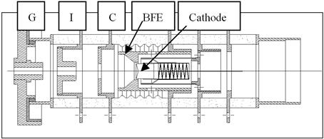
Fig. 2 (a). Schematic diagram of a multi-electrode gun assembly with G: ground anode, I: Ion-barrier anode, C: control anode, BFE, cathode and heater.
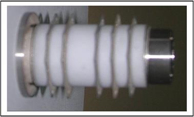
Fig. 2 (b). Photograph of a gun-stack assembly with ceramic insulators.
2.2. Multi-stage Depressed Collector Assembly
Fig. 3 shows schematic diagram of a 4-stage depressed collector assembly for a space TWT with electrode-1 at least depression (-2.5kV) and electrode-4 at maximum depression (-5.5kV) with respect to the ground. Four electrodes of the collector are housed in a ground metallic shell with proper shaped high voltage high purity alumina insulators and four feed-through assemblies. 4-stage collector is used to recover maximum possible kinetic energy of the spent electron beam. The spent beam electrons land at different stages of the collector with minimum energy loss and almost zero back streaming. The collector efficiency is achieved better than 90% not only for DC and saturated RF output power but also for different drive conditions. The collector design includes the effect of secondary electrons. The copper collector electrodes are ion textured as well as carbon sputter coated for suppression of secondary electrons.
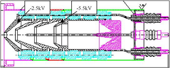
Fig. 3. Schematic diagram of 4-stage collector assembly of a Space TWT with four collector electrodes at -2.5kV, -3.5kV, -4.4kV, -5.5kV wrt ground.
High density high purity graphite (preferably POCO graphite DFP-2, DFP-1C) is also used for collector electrodes as shown in Fig. 4, for a high efficiency low weight collector. This is because the graphite has very low secondary emission coefficient as well as very low density compared to OFHC copper, but extra precautions are needed for complete degassing of graphite electrodes. Technology developed for graphite to ceramic brazing for a brazed collector assembly.
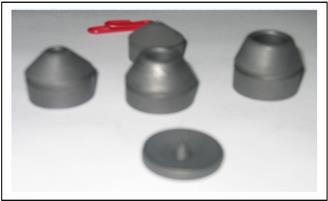
Fig. 4. Photograph of graphite electrodes for 4-stage collector assembly.
2.3. Potting and Packaging
Detailed thermal and structural analyses of electron gun, slow-wave structure (SWS) and multi-stage depressed collector assemblies including complete packaged TWT are carried out [11-13] to ensure satisfactory operation of a tube bearing the extreme space environment of vacuum, thermal radiation, ionizing radiation, plasma and frequent thermal variation from +85°C to –25°C. Base plate and cover for a packaged TWT are designed for effective conduction cooling and well support of all assemblies with minimum size and weight. Isotropic fin-type radiator is designed for the collector assembly for efficient radiation cooling. Al-6061 is used for packaging parts. Magnesium alloy is preferred for packaging, collector radiator and output waveguide for reduced weight. All feed-through of gun and collector assemblies are separately potted using high purity silicon potting compound for long life, low weight and reliable high voltage operation. Isolated potting avoids leakage current through potting compound for long life.
2.4. High Voltage Power Supply
TWT is a multi-electrode vacuum device and it requires a highly sophisticated power supply, known as High Voltage Electronic Power Conditioner (HV-EPC). TWT poses lot of challenges to its Power supply for delivering the RF performance for the intended operational life. HV-EPC [14] is a well regulated power supply used to provide conditioned and isolated voltage rails, with stringent regulation requirements to various electrodes of TWT and make the TWT RF performance independent of solar bus variations that occur due to varying sunlit and eclipse conditions in space. Apart from this, HV-EPC has precisely timed protection and control circuits to safeguard the TWT against all vacuum phenomena like micro-discharge and arcing inside tube. HV-EPC consists of DC-DC converters, DC-AC converter, EMI filters, protection circuits and associated tele-command and telemetry circuits to suit a satellite platform. Detailed thermal and structural analyses of fully packaged TWT with HV-EPC are carried out to ensure successful operation of TWT on-board satellite bearing the extreme space environment of vacuum, thermal radiation, corona, etc.
3. Issues Related to Discharge in Space TWT
The most significant issue for a communication TWT for space applications is the requirement of no discharge over long life of the tube. Micro discharges, spurious, multipactor, on/off switching cycles and other long term effects in space, are to be thoroughly considered for the need of high reliability and long life operation of a space TWT. All materials used inside the vacuum envelope are of high purity, very low gas diffusion rate, low vapor pressure, and avoiding micro-leaks. All parts are electro-polished and chemically cleaned. Also before final assembly most parts are vacuum fired to ensure that outgassing rate is less than 1x10⁻¹⁰ Torr-l/cm2-s even at the actual operating temperature. All materials including epoxy, cable, connector, wire outside vacuum must be of space grade. Thermal issues are carefully analyzed to avoid too high loading on any part to prevent vaporization of material during long life of tube operation. Predicted temperatures at all sensitive points along tube must be well below the material limits. It is necessary for optimizing heat transfer from the hot points. All manufacturing procedures are of space qualified, and there should be high reproducibility during production of space qualified TWTs.
High voltage analysis is done for all ceramic-to-metal joints in the gun and the collector assemblies to ascertain design margin at least twice the operating voltage with leakage current much less than 0.01µA. High voltage stand-off across an insulator assembly is ensured by measuring at least twice the operating voltage under various environmental conditions.
3.1. Avoiding Micro-discharge
Micro-discharge is related to high voltage breakdown in gun and collector assemblies, and is of low energy, lasting microseconds. It is induced by outgassing, field emission, and secondary electrons, and may be caused along the insulator and between electrodes (metal-to-metal). Fig. 5 shows schematic diagram of insulator-metal brazed joints in a high voltage (gun/collector) assembly with positive and negative electrodes and triple junction point [10]. This triple junction is the point where negative metal electrode, insulator and vacuum meet. When high voltage is applied between electrodes, insulator may get charged and may lead to discharge through secondary electron emission (SEE). In this process, electrons with enough energy impact on the insulator surface to eject secondary electrons resulting in a positive charge on the surface. The SEE characteristics of the insulator as well as the structure of the triple junction determine the electric field strength required to cause a surface flashover on the insulator surface in vacuum.
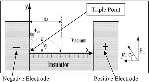
Fig. 5. Schematic diagram of insulator-metal joints with positive and negative electrodes and triple-junction point in a high-voltage assembly.
3.1.1. Minimize Micro-discharge Along the Insulator
All ceramic to metal joints in the gun and collector assemblies are carefully designed with optimized shape and size of the insulators and metallic electrodes for avoiding micro-discharge under all possible conditions. Corrugated high voltage alumina insulators are used for reduced size, weight, and long leakage path. Also, high temperature brazing is employed using either Cu or Au-Cu brazing alloys. All precautions are taken for no sharp edges to avoid high field densities and flashover, and it is ensured that the stray electrons do not reach the insulators and there is a suitable shape of negative electrode (triple junction point). Micro-discharge may occur if there is an electrical field enhancement at negative electrode. Further for minimizing micro-discharge along the insulators, all insulators are perfectly cleaned, and brazed with no sharp edge and any gap.
3.1.2. Minimize Micro-discharge Between Metal to Metal
This is achieved by thorough out gassing of materials, and high voltage withstanding and conditioning. All assemblies are fabricated in clean room preferably of class 100. The TWT is vacuum processed on UHV processing station at high temperature (up to 550°C) over prolonged hours (minimum 100 hours), for achieving ultra-vacuum level (<1x10⁻¹⁰torr). The tube is evacuated both from the gun and collector ends. Residual gas analysis is carried out at different stages of UHV processing of tube to provide details of partial pressures of different constituent gases like H2, He, CO, CO2, N2, and O2.
Self activated non evaporable SAE 175 Zirconium getter [15] is used to maintain ultra-high vacuum inside the sealed tubes to assure high reliability and long lifetime of the tube. These getters are self activated during processing of tube at 550°C. Getter in ring form is mounted on back of the cathode in gun assembly. Getters offer very high pumping speeds for reactive gases such as H2, H20, CO, CO2, N2, and O2, thereby increase significantly the lifetime of a TWT.
3.1.3. High Voltage Withstanding and Conditioning
For high voltage withstanding, there is a need of suitable inter-electrode distance and suitable geometry of all electrodes. Rigorous efforts are required of avoiding surface roughness and whiskers. High voltage conditioning is performed by step by step increase of inter-electrode voltage higher than the nominal operating value. It is also performed by reversing high voltage polarity between two electrodes in the absence of electron beam. The completion of high voltage conditioning reduces leakage current by a big margin. For example, if leakage current is 0.1μA prior to high voltage conditioning, it reduces to 0.01μA after high voltage conditioning. High voltage testing for gun and collector assemblies are performed at different stages of fabrication of the tube: on leak detector during leak testing, on UHV system after outgassing, before initial RF testing of TWT, after potting of gun and collector assemblies, and during thermal vacuum test. The pre burn-in process for limited beam transmission and initial RF testing is carried out with ion pump on at gun end for 400 hrs. Detailed testing of a tube is carried out with increased duty cycle at various operational conditions (on-off, drive power, frequency, and temperature).
3.2. Multipactor Analysis
Multipactor analysis is carried out for all gaps supporting RF power particularly in the output coupler. Real prediction of the multipaction capability of RF output with RF window is analyzed considering complex coaxial structures like a TNC connector with dielectrics, air gaps and complex electric fields inside coaxial RF window. Fig. 6 shows output section of helix SWS with coaxial RF coupler and coaxial ceramic window. Various physical conditions are analyzed that may give rise to the multipactor failure, with special emphasis on power level, frequency range, and gap width likely to cause multipactor. Space TWTs are designed for at least 6dB RF output power margin for avoiding any possibility of multipactor discharge in an operating TWT under various environmental conditions.
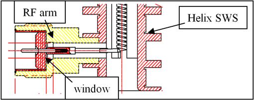
Fig. 6. Coaxial RF Arm and window of a TWT section for Multipactor analysis.
3.3. Critical Facilities
Highly specialized facilities are required for developing space TWTs such as: (i) cathode lab to insure quality, reliability and lifetime of M-type and MM-Type tungsten dispenser cathodes of cathode life more than 200, 000 hours, (ii) variety of furnaces for vacuum and non-vacuum brazing of ceramic and metal assemblies, (iii) vacuum exhaust "bake-out" lab, (iv) high-reliability electronic assembly lab, (v) TWTA test lab, and (vi) fully automated thermal vacuum test chambers. Rationalizing the manufacturing and process controls ensure the long and reliable operation of TWTs onboard the satellite with no discharge. The residual gases in TWTs have several deleterious effects. The gases interfere with the electron beam and cause the electron beam to scatter, and conversely, the electron beam will ionize the gases and the ions will back stream to the cathode and sputter the cathode surface causing emission current degradation.
4. Conclusion
Space TWTs of long life and high reliability are required for satellite communication. The significant factors of long life high reliability operation of a space TWT are directly related to the quality of high voltage insulation and quality of vacuum in the tube. There should not be any discharge in a TWT for all environmental and operating conditions. Discharges and electrical insulation in a space TWT are to be critically analyzed for high reliability and long life operation of a space TWT. Long term effects in space, micro discharges, spurious, multipactor, are thoroughly considered. High voltage analysis is done for all assemblies using ANSYS code to ascertain design margin at least twice the operating voltage with leakage current much less than 0.01µA. To avoid multipactor in an operating tube, sufficient design margin of at least four times the operating RF power output is ensured. Evaluation of no discharge in TWT is performed by quantitatively recording the occurrence of partial discharges during temperature cycling in vacuum for extended periods. C-band 60W space TWT operating at 3kV/75mA, Ku-band 140W space TWT operating at 5.8kV/90mA, and Ka-band 100W space TWT operating at 6.5kV/100mA, are designed for maximum efficiency and long life. Four-stage depressed collector is used to recover more than 90% spent beam energy, and multi-electrodes gun assembly is used. All precautions are taken for no discharge for long life and high reliability of the working tube.
Acknowledgement
The author is thankful to the Director, CSIR-CEERI, Pilani, for his permission for publication of this paper. He is thankful to his TWT group members for their helpful discussions. Author is also thankful to BEL, Bangalore, ISAC (ISRO), Bangalore, and SAC (ISRO), Ahmedabad for their full supports. Thanks are also due to the editorial members of the AASCIT for their helpful comments.
References
- V Srivastava, TK Ghosh, J Akhtar, SN Joshi, Design of high efficiency space TWT, IETE Technical Review, March-April 1999, pp. 249-254.
- V Srivastava, TK Ghosh, RK Sharma, SN Joshi, Indigenous design and development of high efficiency space TWTs, Microwaves & Optoelectronics, ISBN-81-88342-44-0, 2004, Anamaya Publishers, pp 1-8.
- L-3 Electron Technology Inc. for space TWTs, www.L-3.com.
- Thales Group for Space TWTs, www.thalesgroup.com.
- G Kornfeld, Reliability considerations for satellite TWTs, Microwave Journal, vol. 27, Aug. 1984, pp. 113-116.
- JP Calame, DK Abe, Application of advanced material technologies to vacuum electronic devices, Proceedings IEEE, May 1999, pp. 840-864.
- F Hai, KW Paschen, DC partial discharge/environmental test screening of space TWTs, Proceedings of 18th Intersociety Energy Conversion Engineering Conference, American Institute of Chemical Engineers, 1983, p.2216-22.
- W Dürr, J Wegener, E Bosch, RF output multipaction margin of travelling wave tubes, IEEE-IVEC-2011, pp.19-20.
- KW Paschen, F Hai, Automated partial-discharge testing of traveling-wave tubes, 1981STIN.8224430P, May, 1981.
- CH De Tourreil, KD Srivastava, Mechansm of surface charging of high voltage insulators in vacuum, IEEE Trans. on Electrical Insulation, vol. 8, March 1973 pp.17-25.
- M Alaria, V Srivastava, Multipactor analysis of coaxial RF window for Space TWT, International Journal of Microwave and Optical Technology (USA), vol.6, Sept. 2011, pp. 255-258.
- K F Bartos, EB Fite, KA Shalkhauser, GR Sharp, A Three-Dimensional Finite-Element Thermal/Mechanical Analytical Technique for High Performance Traveling Wave Tubes, NASA Technical Paper 3081, 1991.
- RK Sharma, A Bera, V Srivastava, Thermal and Structural Analysis of Electron Gun Assembly for a C-band 60W Space TWT, International Journal of Microwave and Optical Technology, vol. 4, Sept.2009, pp.309-314.
- NV Bijeev, Design and Realization Challenges of Power Supplies for Space TWTs, IEEE-IVEC-2011, Bangalore, pp. 431-432.
- SAES Getters, www.saesgetters.com.
Biography
|  Vishnu Srivastava received Ph. D. degree in Engineering from Lancaster University, U.K., in 1987. He joined CSIR-CEERI, in 1976, and involved with design and development of various high power microwave tubes for Communication and Radars. He developed SUNRAY codes for small-signal and large signal analysis of beam-wave interaction in helix and coupled-cavity TWTs. He received Honorary Fellowship of SERD, New Delhi. Presently, he is emeritus scientist at CEERI. His present interests are in design and development of high efficiency THz vacuum microelectronic devices. Vishnu Srivastava received Ph. D. degree in Engineering from Lancaster University, U.K., in 1987. He joined CSIR-CEERI, in 1976, and involved with design and development of various high power microwave tubes for Communication and Radars. He developed SUNRAY codes for small-signal and large signal analysis of beam-wave interaction in helix and coupled-cavity TWTs. He received Honorary Fellowship of SERD, New Delhi. Presently, he is emeritus scientist at CEERI. His present interests are in design and development of high efficiency THz vacuum microelectronic devices.
|