The Effects of High Energy Electron Beam Radiation Exposure on the Properties of Low Carbon Steel Sheet
M. Farnush
School of Metallurgy & Materials Eng., College of Eng., University of Tehran, Tehran, Iran
Email address
Citation
M. Farnush. The Effects of High Energy Electron Beam Radiation Exposure on the Properties of Low Carbon Steel Sheet. American Journal of Materials Research. Vol. 3, No. 1, 2016, pp. 1-6.
Abstract
This study is concerned with the microstructural analysis and reviewing of wear resistance, of tensile strength and of the surface hardness of low carbon steel sheet alloy by a high energy electron beam. The modified surface microstructure was characterized with methods of optical microscopy (OM), Scanning electron microscopy (SEM), X-ray diffractometry (XRD). Flux was not deposited on low carbon steel sheet alloy, and the electron beam was irradiated on material. Shock hardening on material by high energy electron beam did not improve wear resistance, tensile strength and the surface hardness. These findings suggested that surface shock hardening using high energy electron beam irradiation was not economical and useful for the development of surface shock hardening with improved resistance.
Keywords
High Energy Electron Beam, Radiation, Low Carbon Steel Sheet
1. Introduction
Traditional techniques used to strengthen steel by carbon additions involve case hardening and bake-hardening. Case hardening is related to the diffusion of carbon in bulk materials to increase their surface hardness and strength and it includes many techniques such as: pack carburizing, gas or liquid carburizing and vacuum carburizing. All these processes require temperatures higher than 870°C and hours of processing times [1–3]. These processes are generally used to case-harden the surface of thick materials and cannot easily be applied to harden thin sheets of steel [1]. The traditional process used to strengthen thin sheets of ultra-low carbon steels is bake-hardening. This heat treatment (170°C for 20 min) is performed after the forming step in order to segregate free carbon to the dislocations. However, the increase of yield stress caused by this heat treatment is limited to 50–60 MPa because the amount of carbon initially present in solution in the steel has to be kept low enough to avoid room temperature ageing which would cause Lüder's instabilities to appear during forming [2]. Steel companies are interested in developing new methods which can further increase the yield stress of thin sheets, without compromising the ductility or processing capability. The new approach proposed here is to use a high energy electron beams.
In this study, a process is suggested to create shock hardening on the surface of material by high energy electron beam. Shock hardening cannot improve hardness, wear resistance and tensile strength of low carbon steel alloy. In many steels structures are regions of weakness having a lower strength than the rest of the structure [4]. The strength of these regions can be increased by a post-weld heat treatment or by mechanical working, such as rolling the weld bead and explosive shocking. However, these approaches are often either not practicable or are undesirable. Recently, other methods have become a possibility to increase the wear resistance and tensile strength of in steel alloys such as laser induced shock hardening, electromagnetic wave absorption, and shock hardening by a high energy electron beams (HEEB). The use of a laser beam is attractive because the hardening can be localized to the desired region, is rapid, and can be easily adapted to numerical control.
Shock waves propagating in materials will generate substantial new dislocation density in addition to interacting with existing microstructural features. Hardening mechanism such as formation of dense cellular networks, precipitation hardening, interactions with dispersed oxide particles, and interactions with inclusions all play a role. Twinning is important in BCC metals and alloys, and there have been some reports of shock – induced martensite formation. There have been many experiments that have used conventional shock loading techniques to characterize shock – loaded deformation microstructures [5].
Hardness, dislocation density, stored deformation energy, yield stress, and ultimate tensile strength increase with increasing shock pressure, and then reach a maximum. Cellular dislocation structure [6].
Very similar to copper. At pressures above 1000 kbar, no cellular structure observed, but dislocation density very high [7].
Formation of twins when shocks travel in [1] direction; first ever experimental observation of twining shear in FCC metal [8].
No dislocation cell structure formed up to pressures of 150 kbar, although one is expected. Structure observed was composed of randomly distributed, heavily jogged dislocations, high point defect concentration, and many dislocation loops [9].
As stacking fault energy goes down due to alloying additions, cellular structure gives way to planner dislocation arrays, stacking faults, and twins. [10]
A HEEB offers a unique heat source which may be used for a wide variety of materials processing applications. The unique physical characterizations that make HEEB based processing so attractive are in depth energy penetration, very high average power levels, shock generation capabilities and potential for atmospheric or inert gas environmental operations. High energy electrons penetrate several millimeters into most materials, allowing subsurface heat treatment. Rapid energy deposition produces moderate to strong shocks in many materials, and many potential applications exist which exploit this phenomena [5].
2. Experimental Methods
The material studied in the present paper is low carbon steel sheet alloy EN 1020 ST 12 having the following composition:
Table 1. Composition of low carbon steel sheet alloy EN 1020 ST 12.
| C | Si | Mn | P | S | Cr | Ni | Mo | Cu | V | W |
| 0.01 | 0.006 | 0.10 | 0.007 | 0.005 | 0.01 | 0.005 | 0.01 | 0.008 | None | None |
| Ti | Co | Al | Sn | Pb | As | Sb | Zr | Nb | S | Fe |
| 0.023 | None | 0.023 | 0.004 | Trace | None | None | None | 0.012 | None | Base |
HEEB treatment was carried out using an electron beam source named "Rudotron". Rudotron TT200 has external energy 10Mev and 5 Mev and Maximum Power is 100KW. There are nine section in Rudotron 1) main part 2) RF 3) Cooling system 4) Loop maintains 5) Magnetic 6) Vacuum system 7) Electronic Gun 8) 10 Mev external 9) 5 Mev external. Energy of Electron beam was 10 Mev in this research. The sample was irradiated under dose of 80 KGY.
Prior to HEEB treatment, the sample was cut into disc with dimension of 30 mm x 30 mm x 5 mm and the surface was mechanically grounded and polished.
Microstructure formed in the near – surface layer of untreated and treated specimens were examined with scanning electron microscopy (SEM) from the surface of the samples. X-ray diffraction (XRD) measurements were carried out to detect the phase changes in the surface layers.
The tribological tests were made utilizing a pin-on-disc wear device. The Steel disc is fixed by a clamping device and then pressed on a rotating surface with a constant force. The disc specimen which is made up of EN 1020 ST 12 alloy to be investigated has a square contact area of 9 cm². The rotating 52100 steel disc was grinded to a desired surface roughness. The applied force was 20 N with a sliding velocity of 0.4 m/s and the distance was 1Km. The test results is based on the coefficient of friction which is monitored as a function of Slip distance.
The tensile strength tests were made with velocity of 10 mm/min and the diameters were .7mm.
3. Results
3.1. XRD
XRD analysis of EN 1020 ST 12 alloy was carried out before and after radiation. For initial state, the amount of three peaks Fe, CoFe and Cr are shown in Table 2.
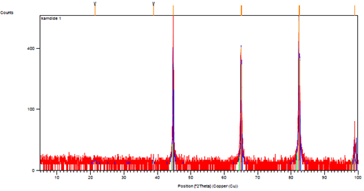
Fig. 1. XRD pattern of EN 1020 ST 12 alloy before irradiation on a TERRA field-portable XRD instrument, used to determine the 2θ-dependent peak profiles needed to simulate instrument-dependent standard patterns.
Table 2. The amount of peaks in EN 1020 ST 12 alloy before irradiation.
| Visible | Ref. Code | Score | Compound Name | Displaceme nt [02Th.] | Scale Factor | Chemical Formula |
| 0 | 00-006-0696 | 48 | Ferrite | 0.000 | 1.030 | Fe |
| 0 | 00-049-1567 | 39 | Cobalt Iron | 0.000 | 0.265 | CoFe |
| 0 | 00-006-0694 | 16 | Chromium, syn | 0.000 | 0.025 | Cr |
For irradiated state, the amount of four peaks Fe, CoFe,AlN and Cr are shown in Table 2. The peak AlN was the reason of error in test of XRD.
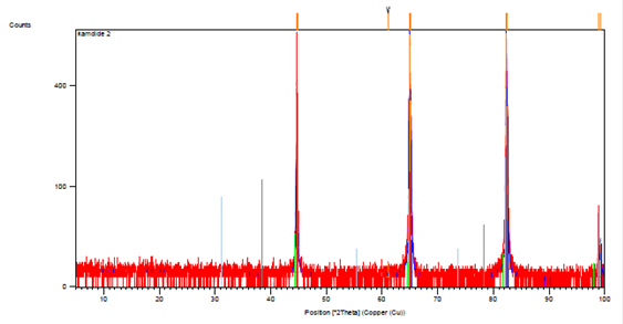
Fig. 2. XRD pattern of EN 1020 ST 12 alloy after irradiation on a TERRA field-portable XRD instrument, used to determine the 2θ-dependent peak profiles needed to simulate instrument-dependent standard patterns.
Table 3. The amount of peaks in EN 1020 ST 12 alloy after irradiation.
| Visible | Ref. Code | Score | Compound Name | Displaceme nt [02Th.] | Scale Factor | Chemical Formula |
| 0 | 00-006-0696 | 50 | Ferrite | 0.000 | 0.977 | Fe |
| 0 | 00-049-1567 | 33 | Cobalt Iron | 0.000 | 0.162 | CoFe |
| 0 | 00-006-0694 | 12 | Chromium, syn | 0.000 | 0.040 | Cr |
| 0 | 00-046-1200 | 44 | Aluminum Nitride | 0.000 | 0.566 | AlN |
3.2. SEM
Figure 3 is SEM images for irradiated and non-irradiated samples in 3000x magnification. A comparison between irradiated and non-irradiated samples reveals that the high density electron of short durations induce dynamic field in the surface layers giving rise to superfast shock and possible moving dislocations. This is evident from thecracks and crater-like morphology on the surface of the irradiated sample. The crater-like morphology, which is typical phenomenon of metallic materials after HEEB treatment is observed on the irradiated surface.
Craters are the result of the eruptions occurred in the subsurface layer of a target material when treated by the high energy electron beam.
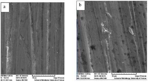
Fig. 3. Micrographs of the surfaces and cross-section of EN 1020 ST 12 alloy before and after radiation, showing the different microstructure in different conditions: (a) initial sample; (b) irradiated sample for 3000X shows crater-like morphology on the surface of the irradiated sample.
3.3. Optical Microscopy
To prepare, each of samples were mounted and used sand papers. Diamond paste (6 Micron) was used for polishing. We used HF 4% for etching. Initial and irradiated samples are shown in the following figures. Both have ferrite and perlite but the amount of ferrite in irradiated sample is more than it in initial sample.
If the amount of carbon in steel decreases, the amount of ferrite increases and the amount of perlite decreases until the steel consists entirely of ferrite. This state occurs when the steel contains approximately 0.025% carbon.
The properties of irons and steels are linked to the chemical composition, processing path, and resulting microstructure of the material; this correspondence has been known since the early part of the twentieth century. For a particular iron and steel composition, most properties depend on microstructure. These properties are called structure-sensitive properties, for example, yield strength and hardness.
The two types of solid solutions impart different characteristics to ferrite. For example, interstitial elements like carbon and nitrogen can easily diffuse through the open bcc lattice, whereas substitutional elements like manganese and nickel diffuse with great difficulty. Therefore, an interstitial solid solution of iron and carbon responds quickly during heat treatment or shock hardening, whereas substitutional solid solutions behave sluggishly during heat treatment, such as in homogenization.
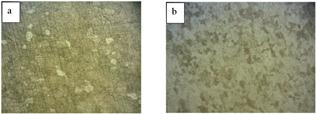
Fig. 4. Metallography of the surfaces and cross-section of EN 1020 ST 12 alloy before and after radiation, showing the different microstructure in different conditions: a) initial sample and b) irritated sample for 250X.
3.4. Wear Result
Rapid energy deposition sometimes cannot lead to very large pressure rise within a material.Subsequent to shock treatment, have not been attributed to the increase in dislocation density and grain-boundary precipitation produced due to shock deformation. Dislocations and grain boundaries were not assumed to act as precipitation sites and an increase in dislocation density.
Shock waves propagating in materials will not generate substantial new dislocation density in addition to interacting with existing micro structural features. Hardening mechanisms such as formation of dense cellular networks, precipitation hardening interactions with dispersed silicon particles and interactions with inclusions all play not a roll.
Table 4. Values for initial and irradiated EN 1020 ST alloy.
| Sample | Primary Mass | Final Mass | Mass Loss |
| Initial | 19.4046 | 19.3780 | 0.0266 |
| Irradiated | 19.1239 | 19.0936 | 0.0303 |
As we can notice from Table 4, the coefficient of friction for initial sample shows less oscillation than irritated sample and reaches lower levels at the first 300 meters. This stability of coefficient of friction for initial sample leads to improved wear resistance.
The comparison between Mass losses of samples in ‘pin on disc’ test also would does not give us a better aspect in usefulness of electron beam irradiation and shock hardening.
Hardness, dislocation density, stored deformation energy and wear resistance decrease with applied shock pressure.
3.5. Tensile Strength Test
The ultimate tensile strength (UTS) of specimens were determined from the test data. In this work, tensile samples were kept at room temperature before testing their tensile properties and the strength rate was constant during the tests.
With due attention to Fig. 6 and Fig. 5 perceived, the irradiated sample with 230 Mpa ultimate tensile strength improved comparably versus the initial sample with 240 Mpa ultimate tensile strength.
The influence of solid-solution elements on the yield strength of ferrite is shown that one can clearly see the strong effect of carbon on increasing the strength of ferrite.
The substitutional solid solution elements of silicon, copper, manganese, molybdenum, nickel, aluminum, and chromium are shown to have far less effect as ferrite strengtheners than the interstitial elements. In fact, chromium, nickel, and aluminum in solid solution have very little influence on the strength of ferrite.
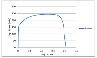
Fig. 5. Stress history inside polyurea of initial sample at the 240 Mpa ultimate tensile strength. The peak of the positive stress was taken as the spall strength of polyurea.
In addition to carbon (and other solid-solution elements), the strength of a ferritic steel is also determined by its grain size according to the Hall-Petch relationship: σy = σ0 + ky d-1/2
Where σy is the yield strength (in MPa), σ0 is aconstant, ky is a constant, and d is the grain diameter (in mm). The grain diameter is a measurement of size of the ferrite grains in the microstructure. This relationship is extremely important for understanding structure-property relationships in steels. Control of grain size through thermomechanical treatment, heat treatment, and/or microalloying is vital to the control of strength and toughness of most steels.
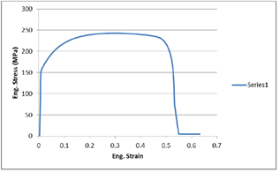
Fig. 6. Stress history inside polyurea of irradiated sample at the 230 Mpa ultimate tensile strength. The peak of the positive stress was taken as the spall strength of polyurea.
3.6. Hardness Test
Macrohardness is 81 Hv in initial sample and 72.5 Hv in irradiated sample. As you see the percentage of ferrite and pearlite are 53.4 and 48.8 in initial sample, 79.6 and 21.6 in irradiated sample. The reason of decreasing hardness in irradiated sample increasing ferrite in irradiated sample.
4. Discussion
High Energy Electron Beam offer significant advantages for processing of advanced, highly engineered materials. HEEBs can create useful materials processing conditions by providing high power levels. Allowing for shock wave generation, and control over temperature profiles. Shock hardening, dynamic consolidation, net shape casting, deep penetration brazing, and heat treatment are all processing areas that are being actively investigated. Shock hardening has been demonstrated on Aluminum with no detectable surface damage. HEEB processing doesn’t offer a potentially useful means of hardening components fabricated from low carbon steel sheet alloys.
5. Conclusions
This research has examined the effect of HEEB treatment for modifying the surface of EN 1020 ST 12 alloy. The major results are summarized as follows:
1) Electron beam irradiation under dose of 80KGY does not change the formation of crystal and does not produce any significant composition.
2) HEEB treatment causes cracks and crater-like morphology on the surface of the irradiated sample due to superfast shock applied by electron beams.
3) Shock hardening did not improve hardness, wear resistance and tensile strength by stabilizing the coefficient of friction.
References
- F.C. Campbell, Elements of Metallurgy and Engineering Alloys, ASM International – The Materials Information Society.
- L. Baker, S. Daniel, J. Parker, Metallurgy and processing of ultra-low carbon bake hardening steels, Mater. Sci. Technol. 18 (2002) 355–368.
- S.R. Elmi Hosseini, Simulation of case depth of cementation steels according to Fick's laws, J. Iron Steel Res. Int. 19 (11) (2012) 71–78.
- M. Farnush, 4th International Conference on Industrial Tools, Bled, 295-299; 2003, Slovenia.
- R. Dave, D. L. Goodman, M. Farnush, T. W. Eagar, and K. C. Russell: Int. Conf. on "Beam processing of advanced materials", Pennsylvania, 537-551; 1993, The Minerals, Metals and Materials Society (TMS), Warrendate, PA, USA.
- B. S. Yilbas, S. Z. Shuja, A. Arif, M. A. Gondal: J Matter. Processing Technology, 2003, 135,1, 1, 6-17.
- D. J. O’Keeffe, D. J. Pastine, "A Practical Guide toGrȕneisen Equations of State," Metallurgical Effects at High Strain Rates, (New York: Plenum Press, 1973) p.157.
- N. C. Christofilos et al, "High Current Linear Induction Accelerator for Electrons," the review of Scientific Instrument, 35(7) (1964), 886-890.
- D. L. Brix, "Use of Induction Linacs with Nonlinear Magnetic Drives as High Average Power Accelerators," UCRL – 90878.
- H. P. Kirchner, "strengthening of Ceramics," (New York: Marcel Dekker, 1979).