Experimental Study and Modeling of Polytetrafluoroethylene (PTFE) and Hydroxyapatite Biocomposite Surface Treatment Using Selective Laser Sintering
M. E. Khosroshahi1, 2, *, H. Safaralizadeh3, A. Anzanpour1
1Laser and Nanobiophotonics Laboratory, Biomaterial Group, Faculty of Biomedical Engineering, Amirkabir University of Technology, Tehran, Iran
2Department of Mechanical & Industrial Engineering, University of Toronto, Toronto, Canada
3Department of Mechanical Engineering, Amirkabir University of Technology, Tehran, Iran
Email address

(M. E. Khosroshahi)
Citation
M. E. Khosroshahi, H. Safaralizadeh, A. Anzanpour. Experimental Study and Modeling of Polytetrafluoroethylene (PTFE) and Hydroxyapatite Biocomposite Surface Treatment Using Selective Laser Sintering. AASCIT Journal of Materials. Vol. 1, No. 4, 2015, pp. 75-82.
Abstract
The selective laser sintering (SLS) is a rapid prototyping (RP) process which uses laser surface treatment to produce consolidation of powder materials. To obtain an efficient SLS, the optical parameters such as laser power, scanning velocity as well as the material properties must be optimized. In this paper, the SLS of biocomposite of Hydroxyapatite (HA) and polytetrafluoroethylene (PTFE) as secondary polymeric binder is investigated. Microstructural assessments of the samples were conducted using scanning electron microscopy (SEM). To study the effect of laser power on the strength of specimens, pressure test were carried out. Depth of sintering layer and its correlation with laser power numerically is explored. In our case, the best sintering condition was achieved at 3 W and 1 mm/s.
Keywords
Selective Laser Sintering, Rapid Prototyping, Biocomposite, Polytetrafluoroethylene, Hydroxyapatite
1. Introduction
The use of lasers in materials processing has become widespread and well established over the years in different fields [1-4]. Rapid prototyping (RP) which uses a laser as a heat source to sinter parts is an advanced manufacturing technology commercialized in the middle of 1980s. These methods have great effect in the shorten of design - manufacturing cycle time, therefore reducing the cost of production and increasing competitiveness [5,6]. SLS is a powder based RP technique where data is created by computer aided design (CAD) from a solid modeling environment to generate 3 - D physical objects. RP systems process CAD data by mathematically slicing the computer model of final desired object into thin even layers. During SLS operation, the laser beam is selectively scanned over the powder surface following the cross sectional profiles carried by the slice data. The interaction of the laser beam with the powder increases the powder temperature to melting point and causes the particles to bind together to form a solid mass. Subsequently, the new layers are built directly on top of previously sintered layer. [7]. The importance of SLS is mainly because of it real potential in the production of complex 3D objects and broad range of material to be used. Generally, it is believed that any material that can be densified by traditional sintering techniques can be processed by SLS.
Advantages of SLS over other rapid prototyping methods include high degree of controllability, the use of inexpensive and safe materials with a wide variety form polymers, to metals and no need to support the parts during the fabrication process [7,8]. SLS also, allows in principal the possibility to fabricate compositional gradients in materials [9,10]. From an energy standpoint Franco et al [11] showed that the SLS potentially can be an environmentally suitable alternative to conventional processes where it uses less energy than other fabrication processes. Some disadvantages may include the fairly rough surface finish of part and that the part itself can be porous with various density [5,12].
It was claimed that the powder characteristics are directly related to fabrication parameters in SLS operation [13,14]. It is [15] demonstrated that SLS has the capability of controlling the densification mechanism and microstructural evolution by adjusting energy input and processing parameters in SLS of Al - 12Si powder. It is also revealed that both powder properties and fabrication
parameters have a strong effect on the mechanical properties and surface features for SLS parts. The structure as well as properties of the parts to be manufactured by SLS should be considered according to their application [12,16]. Interestingly, SLS process have been widely investigated in the biomedical engineering where it enables production of scaffolds in different size and shape [4,17,20]. One such example is the increasing tendency in the use of polymeric material in SLS operation as substrate with metallic or ceramic materials [21-23]. This is due to their low melting temperature, melting flow control, increase of composite toughness and low rate of degradation as a bioimplant. Polymers in comparison with metals and ceramics have much less strength but their strength will enhance through blending with metals and ceramics.
Polymers in comparison with metals and ceramics have much less strength but their strength can be enhanced by blending metals and ceramics. In an investigation [24] bone used as a model material to described the potential of SLS in fabricating nanocomposite scaffolds for bone tissue engineering. It was found that the mechanical properties of both the polymer and nanocomposite scaffolds decreased gradually after their immersion in PBS at 37°C. Further studies by use of computer - aided system for tissue scaffolds (CASTS) and SLS have demonstrated the feasibility of fabricating a scaffold with low stiffness for cardiac tissue engineering using a predetermined design automation method [25]. This work addresses the experimental and theoretical analysis of selective laser sintering of hydroxyapatite, as an important compatible material in human body, at different optical conditions with PTFE as a polymeric binder.
2. Materials and Methods
2.1. Poly (Tetrafluoroethylene) (PTFE)
Poly (tetrafluoroethylene) is a thermoplastic polymer with properties considerably influenced by the processing conditions and polymer grades. After processing, cooling conditions determine the crystallinity of the polymer. Its slow cooling rate leads to higher crystallinity which affects the physical properties PTFE (or Teflon). PTFE is a bioinert material which has the lowest coefficient of friction among all the solid materials and has limited application in structural components because of the low modulus of elasticity. It is a tough and flexible material with moderate tensile strength and excellent resistance to heat and chemicals. PTFEs has a low abrasion resistance and the thermal stability is excellent up to 300°C but it is decomposes above 350°C. PTFE powder with a specified average particle size of 55 µm under the brand name of Aldrich (Mereck index 12, 7743) was used in this research. Some of the properties of the PTFE are tabulated in Table 1.
Table 1. Physical properties of PTFE and HA.
| Properties | PTFE | HA |
| Thermal conductivity (K) | 0.25 W/m.k | 0.125 W/m.k |
| Density (ρ) | 2100 kg/m3 | 3156 kg/m3 |
| Heat capacity (Cp) | 1050 J/kg.K | 3592 J/kg.K |
| Melting temperature (Tm) | 327°C | 1100°C |
2.2. Hydroxyapatite (HA)
Hydroxyapatite (Ca10 (PO4)6 (OH)2) is a non - carcinogenic bioceramic with high modulus of elasticity which is widely used as bone replacement materials in orthopedic surgery. HA powder used in this research was synthesized in the Material and Energy Research Center - Tehran. The powder size distribution was studied by image processing and showed an average size of 66 µm for using an optical microscopy (Olympus - CX41). This analysis showed that the average size of particles is 66 µm. Some of the HA physical properties are listed in Table 1.
2.3. Irradiation Laser
For sintering operation, a 30W CW CO2 laser (SM MEDICAL Captain 30) with a Gaussian output beam distribution and wavelength of 10.6 µm was used to irradiate the samples. The beam was focused by a 100 mm hand piece manipulator to a desirable spot size. HA has a high absorption coefficient at this wavelength. Figure 1a indicates the home - built XY scanning unit which was used for SLS purpose where 1 - D and 2 - D scanning is schematically shown in Fig. 1 (b, c).
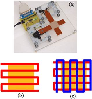
Fig. 1. Scanning unit for laser sintering (a) and 1 - D (b), 2 - D (c) scanning.
3. Modeling
3.1. Heat Transfer Analysis in SLS Process
SLS is a heat transfer process in which the polymer powder is heated rapidly by laser and cools down naturally. SLS process belong to a three - dimensional unsteady heat transfer problem [5]. It was shown by that [26] temperature distribution in a semi - infinite solid for a uniform strip heat source moving at a constant velocity can be approximated by the 1 - D semi - infinite model. To come up this, it is needed that N at equation 1 become greater than 3.9.
N = v r0 / Dt (1)
In this equation v is scan velocity, r0 is radius of laser spot and Dt is thermal diffusivity coefficient. Sun et al. [27] demonstrate by comparison of 1 - D and 3 - D temperature distribution that there is no remarkable difference in the sintering depth and temperature profile in powder. One - dimensional heat conduction equation is described by the following relation:
 (2)
(2)
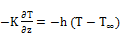
Where ρ is the composite density, CP is the specific heat of composite, T is the temperature, t is the sample exposure time, K is the thermal conductivity and Q is the heat generated in the physical body because of depolymerization. Nelson et al. [28] used the following neumann condition on the boundaries for sintering of ploycarbonate:
 (3)
(3)
 ,
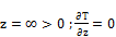
,  ;
; 

,  ;
; 
 (4)
(4)
In the above relations, z is the linear distance up to surface of specimen, α is the material absorption coefficient at laser wavelength, I is the average of laser beam intensity, τ is the laser pulse duration, h is the heat transfer coefficient, and T∞ is the ambient temperature.
3.2. Laser Irradiation Modeling
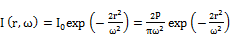
For a complete description of SLS process, distribution of heat generated by laser incidence must be taken into account which requires the modeling of laser - material interaction. By assuming a Gaussian laser beam, the laser beam intensity relation is
 (5)
(5)
Where I0 is the initial intensity, r is the radial distance up to center of beam, ω is the radius of laser beam, and P is the laser power which can be approximately calculated by the following equation:
 (6)
(6)
Where D is the diameter of laser beam on the part bed, Tm is the melting temperature, Tb is the part bed temperature, lf is the latent melting heat, and R is the reflectivity fraction of laser beam reflected by the powder surface. Laser fluence is directly proportional to laser power and inversely proportional to scanning velocity, [29].
 (7)
(7)
Where f is the conversion factor and γ is the scanning distance which should not exceed the diameter of laser beam diameter on the sample surface.
3.3. Powder Bed Material Modeling
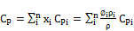
To model thermal binding of polymer powder grains, analysis of physical characteristics of composite powder is required. Widely used equations to calculate the density of composite is
 (8)
(8)
Where  is the volume fraction of the components. Specific heat of the composite is determined from averaging of mass of each components
 (9)
(9)
Zehner et al. [30] proposed a model for thermal conductivity of powder substrate in the SLS process. In this model which is developed for high temperature operations, conduction, convection, and radiation effects within the powder bed are considered.
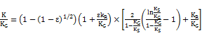 (10)
(10)
where KG is the conductivity of gas, KS is the conductivity of the powder material,  is the porosity of bed, and KR is related to radiation effects.
 (11)
(11)
 (12)
(12)
Where R is reflection coefficient of powder surface,  is the Stefan - Boltzmann constant, DP is the diameter of the particles, Tb is the part bed temperature, and
  is the density of powder material.
3.4. Experimental Procedure
Before the samples treatment, the laser output beam was measured at different distance. Figure 2 shows the variation of spot size with the distance from the articulated arm tip. Clearly, as expected the beam divergence increases with distance which in turn affects the power density on the sample surface and hence the quality of sintering. In our case, the beam spot size was varied suitably to obtain different values of fluence (Jcm- 2).
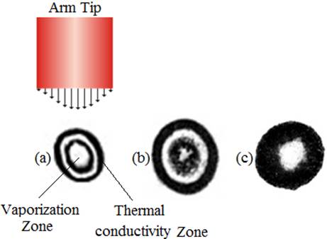
Fig. 2. The divergence of laser beam and its effect on the interaction. (a) at focal point, 2ω= 0.6μm, (b) at 50 mm, 2ω= 2.1mm and (c) at 100 mm, 2ω =2.2 mm.
A mixture of PTFE/HA was produced by physically blending pure PTFE and HA powders with 20 wt% HA content filled in a mould with 5×5×1 mm dimension. As PTFE is a bioinert material, the addition of HA particles will improve the bioactivity of the composite. In this study scanning space is 1.3 mm.
The surface of samples were studied after treatment for change of texture, discolouring and possible melting using the optical microscopy. Finer studies of SLS - fabricated parts were carried out using scanning electron microscopy (SEM), LEO 440i, to characterize the individual parts and to analysis the surface morphology and microstructure of the sintered specimens. For analyzing the effect of laser power on the strength of specimens, pressure test was carried out. A finite element was used to study the optimal processing parameters for SLS, here the parts are modeled as porous. Strength analysis of samples demonstrated a relation between the strength of SLS built parts, laser power and scanning velocity. Compressive strength is calculated by dividing the maximum load by the original cross - sectional area of a specimen.
4. Results and Discussion
Surface treatment of samples was accompanied by a colour change as they altered from white to brown, Fig. 3. The colour change was more significant at lower scanning velocity and higher laser power. However, as power increased, the size of material porosity and its distribution on the surface was significantly decreased. This can be explained by the fact that at higher powers one expects higher temperatures followed by subsequent PTFE melting which in effect covers the porosities.
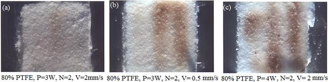
Fig. 3. Optical microscopy of composite surface with 20% HA and 80% PTFE, (a) 3W, Ns=2, V=2 mm s- 1, (b) 3 W, N=2, V= 0.5 mm s- 1, (c) 4W, N=2, V= 2 mm s- 1.
This is further confirmed by analyzing SEM microstructures in Fig. 4 which shows the porosity or uniformity of sample surface is closely related to melting rate of substrate PTFE polymer. In the sintering process laser can have a high power and low scanning velocity thus, the molten PTFE will have a low viscosity and moderately high drift flow filling up the pores around HA particles.
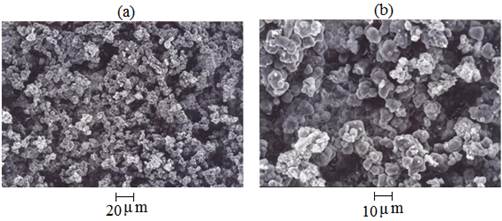
Fig. 4. SEM microstructure of 20% HA and 80% PTFE composite at 2 W, 200x (a), 600x (b).
Fig. 5 illustrates the micrograph of a sample processed at 3 W, 2 mm/s velocity, and scanning space of 1.3 mm. For this sample the laser spot diameter was 2 mm and its distance from the arm tip focal point was 100 mm. As it can be seen, PTFE particles are melted and the liquid phase was rapidly cooled and the molten material bound together on the surface. The irregular and brighter particles in the microstructures are HA particles which did not exhibit any change in their shape due to their higher melting point. As seen in Fig. 5, at higher laser power PTFE particles receives more heat which quickly increases its temperature and this in turn causes the viscosity of liquid phase to decrease hence the coalescence of particles is enhanced leading to less porosity compared with that in Fig. 4.
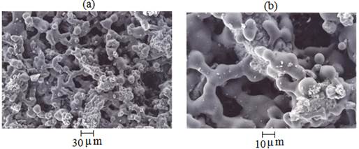
Fig. 5. SEM microstructure of 20% HA and 80% PTFE composite, 3W, N=2, V= 2 mm s- 1, 200x (a), 600x (b).
Fig. 6 indicates the microstructure of sample irradiated even higher laser power of 4 W. The SEM micrographs clearly reveals that the porous space is filled more evenly and smoothly compared with figures 4 and 5. A very smooth surface was produced and the HA particles are completely surrounded by the PTFE pool. This again can be explained on the account of higher temperature gradient which melts greater amount of powder at the surface and depth of sample.
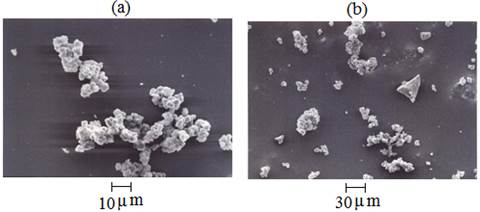
Fig. 6. SEM microstructure of 20% HA and 80% PTFE composite at 4 W, N=2, V= 2 mm s- 1, 200x (a), 600x (b).
Another influential parameter in analyzing the sintering process is the tensile strength, σ′ of the material after treatment. As it is seen in Fig. 7, it initially increases with increasing the laser power where it reaches its maximum value of 3 MPa at 3 W. However, beyond this value, the strength decreases to just above 2 MPa at 4 W. It seems that there is an optimum value of power where the powder bonding is neither too weak due to unmelted grains nor due to overheating and possibly a chemical change in the structure of PTFE causing degradation of the molecular chains.
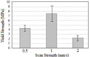
Fig. 7. Yield strength diagram versus scan velocity, N= 2.
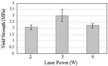
Fig. 8. Yield strength diagram versus laser power, N=2.
Similarly, Fig. 8 indicated the yield strength as a function of scan velocity. Again it increases with velocity from 4 MPa to maximum value of 8 MPa which from there onwards it declines at higher velocity where it drops to 2 MPa at 3 mm/s. Low powers or high scan velocity will prevent the powder particles from reaching to a thermal reaction and a required thermal diffusion which effectively implies an untreated area with raw composition hence low yield strength. The maximum difference in the yield strength in Fig. 7 is 18% in comparison to 59% of Fig. 8. This indicates the importance of laser power in SLS operation. Figure 9 shows the stress - strain curve for compression test of the sample with highest strength value obtained in Fig. 8 which was sintered twice with 3W laser power at 1mm/s. A non - linear behaviour is observed at the strain threshold of 0.6 beyond which the material exhibits a sharp rise in stress load and strain increase.
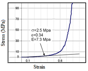
Fig. 9. Stress - Strain diagram of the sample treated with 3 W laser power, N= 2, V=1mm/s.
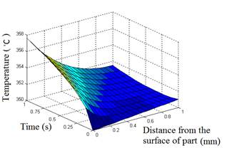
Fig. 10. Distribution of temperature in samples body during laser incidence.
The sintering depth of the composite powder versus time and temperature is illustrated in Fig. 10. This diagram is a solution for equation (2) which shows that at the moment of laser irradiation of the sample surface, it raises its temperature from room temperature to about 350° C which can easily cause a phase transition from solid to liquid. When the sampe position is scanned for number of times, the temperture rises to 358° C which can thermally degrades PTFE. The temperature distribution shows that porosity is anisotropic hence the thermal load vectors acting non - uniformly throughout the sample. Because upper layers absorb more photons and produce more heat than lower layers, therefore the particles are expected to be loosely bound.
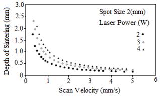
Fig. 11. Depth of laser sintering versus scan velocity and laser power.
Correlation between the scan velocity and depth of sintering as well as laser power is displayed in Fig. 11. It is evident that constant scan velocity higher laser power causes higher degree of sintering while at constant laser power sintering decreases with increase in scan velocity. Thus, based on figures 8 and 11, we can deduce and confirm our previous argument that higher yield strength does not necessairly imply a higher sintering level. Figure 12 illustrates the variation of surface temperature with scan velocity where it linearly increases up to 700°C at 6 W and beyond that a gradual deviation is observed.
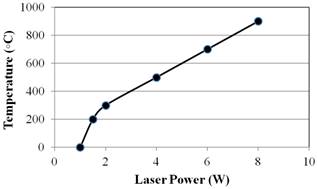
Fig. 12. Produced temperature in the surface of samples versus laser power.
5. Conclusion
Modeling and experimental results of selective laser sintering of PTFE and HA as a biocompatible composite are described. The effects of different laser power and scan velocity on the microstructure properties of samples are studied. The results showed that the yield strength of composite during sintering varies non - linearly with both scan velocity and laser power with the latter being more influential in SLS process. At higher powers PTFE particles are melted and cover the porous regions more efficiently. At constant scan velocity higher laser power causes higher degree of sintering while at constant laser power sintering decreases with increase in scan velocity. Also, higher yield strength does not necessairly imply a higher sintering level. At a given laser wavelength for an efficient SLS processing, the optical parameters must be carfefully optimized.
References
- Xiong C X, Wang T, Liu Q H, et al. Study on Preparation and Structure Characterization of Nano - crystalline poly (vinylchloride) [J]. J Appl Polym Sci, 2004.19 (1): 563 - 569.
- Montagen J., Sarnet Th., Prat Ch., et al, High intensity KrF excimer laser processing of metal surfaces. Appl. Sur. Sci. 69 (1993) 108 - 114.
- Solla E., Borrajo J., Gonzales, etal Plasma assisted pulsed laser deposition of hydroxyapatite thin films. Appl. Surf. Sci. 248 (2005) 360 - 364.
- Khosroshahi M.E., M. Mahmoodi, H. Saeedinasab, et al, Evaluation of mechanical and electrochemical properties of laser surface modified Ti - 6Al - 4V for biomedical applications: in vitro study. Appl. Surf. Sci. 24 (2008) 209 - 2018.
- Lima M., V. M. Correlo, R. Reis, Micro/nano replication and 3D assembling technique for scaffold fabrication. Mat. Sci. Eng. C 42 (2014) 625 - 218.
- Gibson, D. Shi, Material properties and fabrication parameters in selective laser sintering Process, Rapid Prototyping Journal, 3 (1997) 129 - 136.
- Wiria F., Leong K., Chua C., Modeling of powder particle heat transfer process in selective laser sintering for fabricating tissue engineering scaffolds, Rapid prototyping J. 16 (2010) 400 - 410.
- Tan K., Chua C., Leong K., Cheah C., et al, Scaffold development using selective laser sintering of polyetheretherketon - hydroxyapatite biocomposites blends, Biomat. 24 (2003) 3115 - 3123.
- Hu J., Tosto S., Guo Z., Wang C., Functionally graded material by laser sintering, Lasers in Eng. 12 (2002) 239 - 245.
- Chua C.K., Leong K., Rapid Prototyping: Principles and Applications in Manufacturing, Wiley, NewYork, 1997.
- Costa Santos E., Shiomi M., Osakada K., et al, Rapid manufacturing of metal components by laser forming, Int. J. Machine 46 (2006) 1459 - 1468.
- A. Franco, M. Lanzetta, L. Romoli, Experimental analysis of selective laser sintering of polyamide powders: an energy perspective, Journal of Cleaner Production (2010) 1722 - 1730.
- Lu L., Futh J., Laser Induced Materials and Processes for Rapid Prototyping, Kluwer Publishers, Dordrecht, 2001.
- Badrinarayan B., Barlow J., Effect of processing parameters in SLS of metal - polymer powders, Solid Freeform Fabrication Symposium, Astin - Texas, (1995) 55 - 63.
- Salmoria G., Leite J., Ahrens C., et al, Rapid manufacturing of PA/HDPE blend specimens by selective laser sintering, Microstructural Characterization, Polymer Testing 26 (2007) 361 - 368.
- Olakanmi E., Cochrane R., Dalgarno K., Densification mechanism and microstructural evolution in selective laser sintering of Al–12Si powders, J. of Mat. Proc. Tech. 211 (2011) 113 - 121.
- Wiria F., Leong K., Chua C., Liu Y., Poly - e - caprolactone/Hydroxyapatite for tissue engineering scaffold fabrication via selective laser sintering, Acta materialia 3 (2007) 1 - 12.
- Cappelli E., Orlando S., Sciti D., Montozzi M., Pandolfi L., Ceramic surface modification induced by pulsed laser treatment, Appl. Sur. Sci. 154 - 155 (2000) 682 - 688.
- Sudarmadji N., Tan J., Leong K, et al, Investigation of the mechanical properties and porosity relationships in selective laser –sintered polyhedral for functionally graded scaffolds, Acta Biomater. 7 (2011) 530 - 537.
- Chen Ch., Lee M., Shyu V., et al, Surface modification of polycaprolactone scaffolds fabricated via selective laser sintering for cartilage tissue engineering, Mat. Sci. Eng. C 40 (2014) 389 - 397.
- Tampieir A., Celotti G., Szontagh F., Landi E., Sintering and characterization of HA and TCP bioceramics with control of their strength and phase purity, J. Mat. Sci: Mat. In Med. 8 (1997) 29 - 37.
- Suman Das, Selective laser sintering of polymers, polymer - ceramic composites, Virtual Prototyping & Bio. Manufacturing in Medical Applications, (2008) 229 - 260.
- Kumar S., Kruth J., Composites by rapid prototyping technology, Materials & design 31 (2010) 850 - 856.
- Eosoly S., Brabazon D., Lohfeld S., Looney L., Selective laser sintering of hydroxyapatite/poly - e - caprolactone scaffolds, Acta Biomaterialia 6 (2010) 2511 - 2517.
- Duan B., Wang M., Zhou W., Cheung W., et al, Three - dimensional nanocomposite scaffolds fabricated via selective laser sintering for bone tissue engineering, Acta Biomaterialia 6 (2010) 4495 - 4505.
- Cappelli E., Orlando S., Sciti D., Montozzi M., Pandolfi L.,, Ceramic surface modification induced by pulsed laser treatment, Appl. Surf. Sci., 154 - 155 (2000) 682 - 688.
- Festa R., Manca O., Naso V., A comparison between models of thermal fields in laser and electron beam surface processing, Int. J. Hear Mass Transfer. 31 (1988) 99 - 106.
- Sun M., Physical modeling of the selective laser sintering process, PhD thesis, The University of Texas at Austin, Austin, TX, 1992.
- Nelson J., Joel S., Barlow W., Beaman J., Marcus H., Model of the Selective laser sintering of bisphenol - A polycarbonate, Ind. Eng. Chem. Res., 32 (1993) 2305–2317.
- Yagi S., Kunii D., Studies on effective thermal conductivities in packed beds, AIChE Journal, 3 (1957) 371 - 381.
- Veil N., Balasubramanian B., A thermal model of polymer degradation using selective laser sintering polymer coated ceramic powder, Rapid Prototyping J. 2 (1995) 24 - 40.


